What Is Printed Circuit Assembly and How Does It Work
Printed circuit assembly, often called PCA or PCBA, means putting electronic components onto a printed circuit board to create a working device. You depend on this process every day, whether you use a smartphone, a computer, or a home appliance. Over the past decade, you can see new trends in the industry: machine assembly has replaced most hand assembly, flexible PCBs have become more common, and new technologies like VR/AR help workers assemble boards faster and more accurately. These changes make printed circuit assembly more important than ever in modern electronics.
Key Takeaways
Printed circuit assembly adds electronic parts to a bare board, turning it into a working device you use every day.
The assembly process uses careful steps like solder paste application, component placement, soldering, and testing to ensure reliability.
Two main methods attach parts: Surface Mount Technology (SMT) for small, fast devices and Through-Hole Technology (THT) for strong, heavy-duty parts.
Quality control with inspections and tests catches problems early, making your devices safer and more dependable.
Advanced assembly techniques help create smaller, more powerful electronics that last longer and support new technologies.
What Is Printed Circuit Assembly
Definition
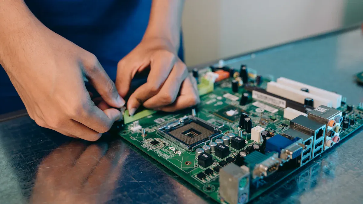
You may wonder what printed circuit assembly means. It is the process where you add electronic components to a bare printed circuit board (PCB). The PCB itself is just a flat board with copper lines, called traces, that connect different points. PCB manufacturing creates this empty board, but it does not have any working parts yet. Printed circuit assembly takes the next step. You place parts like resistors, capacitors, and chips onto the board. Then, you attach them using special machines and soldering methods. This process turns the plain board into a working part of your device.
Note: Printed circuit assembly is different from PCB manufacturing. PCB manufacturing gives you the board with copper traces, but no components. Printed circuit assembly adds the parts and makes the board functional.
You see printed circuit assembly in action every time you use a phone, a computer, or even a remote control. Without this process, your devices would not work.
Purpose
Printed circuit assembly has a clear purpose. It connects and supports all the electronic parts in your device. The copper traces on the board carry signals between the parts. This lets the device do its job, like playing music or sending messages. You rely on printed circuit assembly to make sure each part works together.
Printed circuit assembly does more than just hold parts in place. It helps your device stay reliable and safe. The process uses careful steps, such as placing parts, soldering, and testing. These steps make sure the board works well and lasts a long time. You benefit from this because your devices become more dependable.
Here are some key reasons why printed circuit assembly is essential:
It provides a strong base for parts and connects them with copper traces.
It uses careful steps and special tools to make sure everything works right.
It allows for smaller, more powerful devices by placing parts close together.
Printed circuit assembly supports both simple and complex designs. It lets you enjoy modern electronics that are smaller, faster, and more powerful.
Printed Circuit Assembly Process
Assembly Steps
You can break down the printed circuit assembly process into several important steps. Each step helps turn a bare board into a working electronic device. Here is a typical sequence you might see in a modern assembly line:
Solder Paste Application: You apply solder paste to the pads on the PCB using a stencil. This paste holds the components in place and helps form strong electrical connections.
Solder Paste Inspection (SPI): Machines scan the board to check if the solder paste sits in the right spots and has the correct thickness.
Pick and Place: Automated machines pick up tiny electronic parts and place them onto the solder-pasted pads.
X-ray Inspection: For some special parts, like chips with hidden connections, you use X-rays to check the solder joints before heating.
Reflow Soldering: You heat the board in a special oven. The solder paste melts and creates solid joints between the parts and the board.
Automated Optical Inspection (AOI): Cameras scan the board to look for misplaced parts or bad solder joints.
Through-Hole Component Insertion: You insert larger parts with wire leads into holes on the board. Sometimes, machines help with this step, but people often do it by hand.
Wave or Selective Soldering: You use a wave of molten solder or a focused soldering tool to attach the through-hole parts.
Cleaning and Trimming: You clean off any leftover flux and trim extra wires from the parts.
Post-Assembly Processes: You might test the board, add protective coatings, program chips, or package the finished product for shipping.
Tip: Each step in printed circuit assembly helps make sure your device works well and lasts a long time.
SMT and THT Methods
You will find two main ways to attach parts during printed circuit assembly: Surface Mount Technology (SMT) and Through-Hole Technology (THT). Each method has its own strengths and uses. The table below shows how they compare:
Aspect | Through-Hole Technology (THT) | Surface Mount Technology (SMT) |
|---|---|---|
Inserted into drilled holes and soldered on the other side | Mounted directly onto the PCB surface | |
Mechanical Strength | Strong bonds, good for high-stress uses | Less robust, better for light, compact devices |
Component Size & Density | Larger parts, less crowded boards | Smaller parts, higher density, both sides of PCB usable |
Assembly Process | More manual work, slower, needs drilling and wave soldering | Automated, faster, uses solder paste and reflow ovens |
Cost | Lower setup cost, higher per-unit cost due to labor | Higher setup cost, lower per-unit cost in large volumes |
Application Suitability | Best for industrial, automotive, or high-heat environments | Best for phones, laptops, and high-speed electronics |
Signal Performance | Longer leads, more signal loss | Shorter leads, better for fast signals |
You use THT when you need strong mechanical connections, such as in heavy machinery or cars. SMT works best when you want small, lightweight, and fast devices. SMT lets you place more parts on both sides of the board, which helps make electronics smaller and more powerful.
Inspection and Testing
You need to check each board carefully during and after printed circuit assembly. Inspection and testing help you catch mistakes early and make sure the board works as planned. Here are some common methods you might use:
Inspection/Testing Method | Description |
|---|---|
Boundary Scan Testing | Checks connections between chips without touching the board |
In-Circuit Testing | Measures resistance and checks for open or short circuits using special test equipment |
Flying Probe Test | Uses moving probes and cameras to check connections, great for prototypes |
Automatic X-Ray Inspection | Looks inside chips and under solder joints using X-rays |
Automated Optical Inspection (AOI) | Uses cameras to spot misplaced parts or bad solder joints |
Tin Whisker Testing | Finds tiny metal hairs that could cause shorts |
Optical Microscopy/SEM | Magnifies the board to find small defects or dirt |
PCB Contamination Testing | Checks for leftover chemicals that could harm the board |
Micro-Sectioning Analysis | Cuts and examines the board to find hidden problems |
Functional Testing | Runs the board to see if it works as expected |
Note: Careful inspection and testing help you avoid costly mistakes and keep your devices safe and reliable.
Components and Materials
PCB Structure
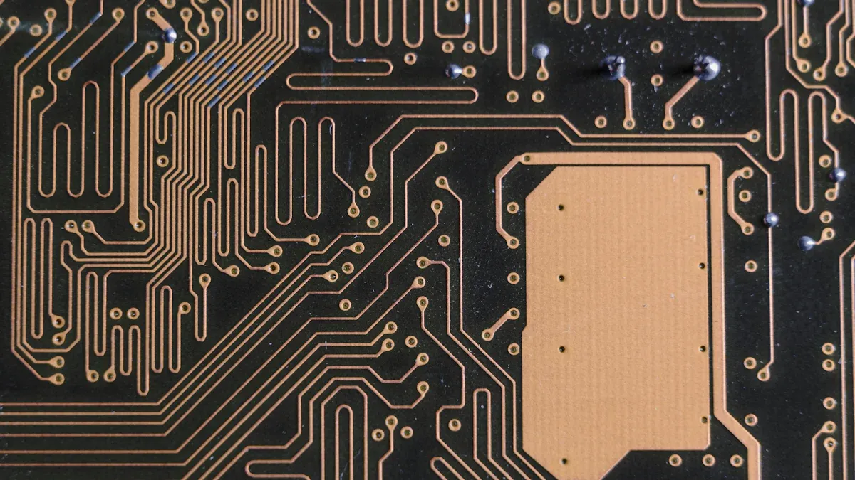
You can think of a printed circuit board (PCB) as a layered sandwich. Each layer has a special job. The main parts include copper layers, insulating materials, and protective coatings. The copper layers carry electricity between components. The substrate, often made from a material called FR-4, gives the board its strength and keeps the layers apart. Solder mask covers the copper to stop short circuits and protect the board during assembly. Silkscreen markings help you see where to place each part.
A typical PCB includes these layers:
Copper Layers: These are the main paths for electricity. You find them on the top, bottom, and sometimes inside the board.
Substrate Layers: These layers act as the backbone. They keep the board strong and safe from electricity.
Solder Mask Layers: This green (or sometimes other color) coating keeps the copper safe from damage and stops unwanted connections.
Copper Pad Layers: These are small spots where you attach electronic parts.
Silkscreen Layers: These white letters and symbols show you where to put each component.
The choice of materials matters. High-quality materials with a high Comparative Tracking Index (CTI) help your board last longer, even in tough places like cars or airplanes. Good materials also make your board safer and more reliable.
Common Components
You use many types of electronic parts on a PCB. Each one has a special job. Here are some of the most common:
Resistors: Control how much current flows.
Capacitors: Store and release energy, often used for filtering.
Integrated Circuits (ICs): Act as the brains, handling complex tasks.
Diodes: Let current flow in only one direction.
Transistors: Switch or amplify signals.
Inductors: Store energy in a magnetic field.
Connectors: Link your board to other devices.
Crystals and Oscillators: Keep time for your circuits.
LEDs: Light up to show status or information.
Switches and Relays: Turn circuits on or off.
Transformers: Change voltage levels.
Component Type | What It Does |
|---|---|
Limits current | |
Capacitor | Stores/releases charge |
IC | Processes signals |
Diode | Controls current direction |
Transistor | Switches/amplifies signals |
Inductor | Stores energy in magnetism |
Connector | Connects to other devices |
Crystal/Oscillator | Sets timing |
LED | Lights up |
Switch/Relay | Turns circuits on/off |
Transformer | Changes voltage |
Choosing the right parts and materials helps you build a board that works well, lasts long, and stays safe.
Quality and Cost
Quality Control
You want your printed circuit assemblies to work every time. Quality control helps you reach this goal. In the industry, you find several standard steps that keep defects low and reliability high:
Solder Paste Inspection (SPI) checks if the solder paste sits in the right place and has the correct amount.
Automated Optical Inspection (AOI) uses cameras to spot missing or misplaced parts and bad solder joints.
X-ray Inspection lets you see hidden connections, especially under chips with many tiny pins.
Functional Circuit Testing (FCT) runs the board as if it were in a real device to make sure it works.
In-Circuit Testing (ICT) checks each part and connection using special probes.
You also see quality systems like ISO 9001 and AS 9100 in many factories. These systems set rules for how to make and check your boards. Skilled workers often get IPC solder training, which helps them make better solder joints and reduce mistakes.
Quality control makes a big difference. When you use these steps, you catch problems early and fix them fast. The chart below shows how better quality control can lower the number of bad boards:
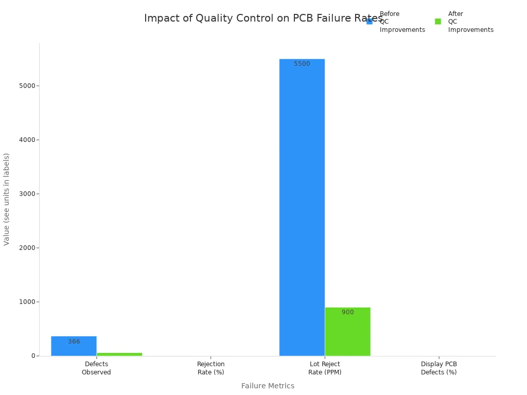
You can see that defects and rejection rates drop a lot after improving quality checks.
Cost Factors
You might wonder why some printed circuit assemblies cost more than others. Many things affect the price:
PCB material and complexity: Special materials and more layers raise costs.
Manufacturing location: Labor costs change by region. Boards made in North America often cost 3 to 4 times more than those made in Asia.
Order quantity and speed: Large orders cost less per board. Rush jobs cost more.
Board size and layer count: Bigger and thicker boards use more materials.
Component type and packaging: Tiny or complex parts like BGAs need careful placement and inspection.
Assembly method: SMT is usually cheaper than through-hole, but mixed methods cost the most.
Here is a table to help you compare:
Assembly Type | Typical Cost Range (per panel) | Notes |
|---|---|---|
$50 - $500 | Best for high-volume, automated production | |
Through-Hole Assembly | $100 - $1,000 | More labor, higher cost |
Mixed Assembly | $150 - $1,500 | Combines both, most expensive |
PCB assembly can make up 30% to 60% of your total electronics cost. If you want to save money, you can design for easier assembly, order in larger quantities, and choose the right technology for your needs.
Importance in Electronics
Role in Devices
Printed circuit assembly shapes the way your electronic devices work every day. You find PCBs at the heart of smartphones, computers, smartwatches, and even home appliances. These assemblies connect all the parts, making sure your device runs smoothly and reliably. The table below shows how printed circuit assembly supports the operation of your favorite gadgets:
Role Aspect | Explanation |
|---|---|
Functional Connectivity | PCB assembly links components, allowing your device to function as one unit. |
Miniaturization & Functionality | Advanced assembly packs more features into smaller spaces, making devices compact and powerful. |
Reliability & Performance | Careful assembly ensures your device works well under different conditions. |
Production Efficiency | Automated assembly speeds up production and reduces mistakes, so you get better products faster. |
Innovation Driver | New assembly methods help bring the latest technology to your hands. |
Quality Control & Testing | Rigorous checks during assembly keep your devices safe and long-lasting. |
You benefit from these roles every time you use a device that fits in your pocket, lasts for years, and performs complex tasks with ease.
Benefits
Printed circuit assembly brings many advantages to modern electronics. You enjoy smaller, lighter, and more powerful devices because of advanced assembly techniques. Here are some key benefits:
PCB assembly allows for a neat and compact layout, replacing messy wiring and saving space.
Surface mount technology (SMT) and miniaturized parts help create thin, portable devices without losing features.
High-density boards let you use gadgets with more functions in the same small size.
Automated assembly improves precision, reduces human error, and speeds up production.
Quality control steps like optical inspection and testing catch problems early, making your devices more reliable.
Miniaturization lowers power use, which means longer battery life and less heat.
Smaller PCBs cut down on material costs and make shipping easier.
Flexible and rigid-flex PCBs support new designs, such as foldable phones and wearable tech.
Strong assembly methods protect devices from dust, moisture, and bumps, so they last longer.
Printed circuit assembly supports innovation, letting you enjoy the latest trends like IoT, AI, and 5G.
Tip: The next time you use your phone or smartwatch, remember that printed circuit assembly makes it possible for your device to be small, smart, and dependable.
You have seen how printed circuit assembly transforms a simple board into a reliable electronic product. This process uses steps like solder paste application, precise component placement, and strict quality control to ensure your devices work well. As technology advances, you can benefit from learning more about new assembly methods, automation, and sustainability.
Explore industry magazines, technical workshops, or certification programs to deepen your knowledge and stay ahead in electronics.
FAQ
What is the difference between PCB and PCBA?
You see a PCB as just the board with copper traces and no parts. A PCBA has all the electronic components attached. PCBA means the board is ready to work in your device.
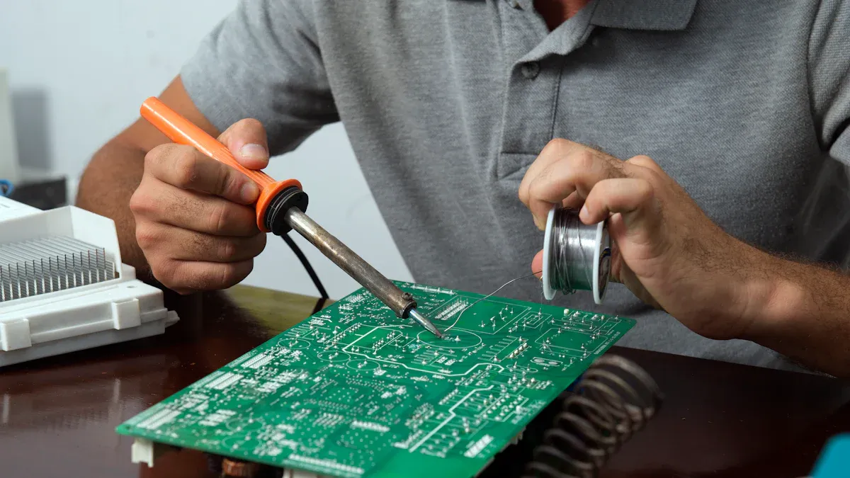
Can you repair a printed circuit assembly if it breaks?
You can repair some PCBAs by replacing damaged parts or fixing broken traces. Simple repairs use soldering tools. Complex boards may need special equipment or expert help.
Why do some devices use both SMT and THT components?
You find both methods on one board when you need strong parts and small parts together. SMT fits tiny chips and saves space. THT gives extra strength for connectors or heavy parts.
How do you keep a PCBA safe from damage?
You protect PCBAs by using coatings, shields, and careful packaging. These steps block moisture, dust, and static. You also avoid bending or dropping the board during use or repair.
See Also
Exploring How Programmable Logic Chips Operate And Function
Understanding The Functionality Of Computer Chips Explained
A Comprehensive Guide To Electronic Digital Integrated Circuits
How Current Controller Chips Work And Their Key Functions
The Role And Operation Of Hotswap Controller Chips Explained
