How to Replace a WQFN40 Switch Chip in a Nintendo Switch Console
You may need to replace a WQFN40 Switch Chip to restore your Nintendo Switch to working order. This repair requires steady hands, proper soldering skills, and specialized tools. Always take safety seriously when working with electronics. Double-check your workspace and gear before you begin. If you have never worked with small components, consider practicing first or seeking help from someone with experience.
Key Takeaways
Always power off your Nintendo Switch and unplug it before starting any repair to avoid electric shock and damage.
Use the right tools like screwdrivers, tweezers, a hot air rework station, and safety gear to make the repair safe and effective.
Work in a static-free environment using an ESD mat and wrist strap to protect delicate components from static damage.
Remove and install the WQFN40 Switch Chip carefully by cleaning pads, aligning the chip correctly, and using controlled heat with a hot air station.
Test your console thoroughly after reassembly to ensure all functions work and fix any issues before finishing.
Tools and Preparation
Required Tools
Before you start, gather all the tools you need for a safe and successful repair. Using the right tools helps you avoid damage and makes the process smoother. Here is a list of essential items:
Tri-point Y00 screwdriver and JIS #000 screwdriver for removing screws of different sizes
Tweezers for handling small parts and connectors
Spudger for prying and disconnecting cables
Microfiber cleaning cloths and isopropyl alcohol for cleaning surfaces
iFixit opening tool for opening the case safely
Thermal paste and K5-PRO viscous thermal paste for reapplying to the heat sink
Hot air rework station for heating and removing surface-mounted chips
60/40 flux core solder for making strong, reliable joints
Fine-tipped soldering iron for precise soldering work
Desoldering braid for removing old solder
Magnifier or microscope (such as the LinkMicro LM210) for seeing small details
ESD mat and wrist strap to protect against static electricity
Safety glasses and gloves for personal protection
Tip: High lead content solder, like 60/40, melts at a lower temperature. This helps you avoid overheating and damaging the board or nearby parts.
Setup Steps
You need to set up your workspace before you begin. Follow these steps to prepare:
Power off your Nintendo Switch completely.
Remove the Joy Con controllers by pressing the locking tabs and sliding them upward.
Use the correct screwdrivers to remove all screws from the back panel. Keep the screws organized.
Flip up the kickstand and take out the microSD card if present.
Carefully lift the rear panel, opening the game card cartridge flap if needed.
Unscrew and remove the microSD card reader. Set it aside safely.
Remove the shield plate by unscrewing and gently prying it up. Note that thermal paste may hold it in place.
Disconnect the battery using a spudger to avoid short circuits.
Remove the heat sink and clean off old thermal paste. Apply new paste when reassembling.
Disconnect ribbon and antenna cables with tweezers or a spudger. Be gentle to avoid damage.
Remove speaker connectors and screws holding the motherboard. Lift the motherboard out carefully.
Understanding the layout of the Nintendo Switch motherboard helps you avoid mistakes. Take photos as you go to remember where each part belongs.
Safety Guidelines
Power Off Console
You must always power off your Nintendo Switch before starting any repair. Unplug the console from any power source. Remove the battery if possible. This step protects you from electric shock. It also keeps the motherboard and other parts safe from damage. Never work on the console while it is plugged in. Even a small amount of electricity can harm sensitive components.
Tip: Double-check that the power light is off. Wait a few minutes after unplugging to let any stored energy drain away.
You should also remove any game cards and microSD cards. Store them in a safe place. This prevents accidental loss or damage during the repair.
Prevent Static
Static electricity can damage the delicate chips inside your Nintendo Switch. You need to work in a static-free environment. Use an ESD (Electrostatic Discharge) mat on your work surface. Wear an ESD wrist strap and connect it to the mat. This setup grounds you and stops static from building up.
Place all tools and parts on the ESD mat.
Avoid wearing clothes that create static, like wool or polyester.
Touch a metal object before handling the motherboard to discharge any static from your body.
Note: Static damage is not always visible. A small zap can ruin a chip without leaving a mark.
Keep your workspace clean and dry. Do not work on carpeted floors. If you follow these steps, you lower the risk of damaging the motherboard or the new chip. Careful handling keeps your repair safe and successful.
Disassembly
Open Console
You need to open your Nintendo Switch with care. Start by placing the console on your ESD mat. Use the correct screwdriver to remove all screws from the back panel. Keep each screw in a small container or on a magnetic mat. This helps you avoid losing any pieces.
Many parts inside the Switch use smart design features. For example:
Plastic snaps hold the case halves together. These snaps keep the seams tight and make opening easier.
The screws all face the same direction. This makes it simple to remember where each one goes.
Some screws are longer or shorter. Pay attention to their locations so you can put them back correctly.
Gently lift the back panel. If you feel resistance, check for hidden screws under the kickstand or near the game card slot. Do not force the panel. Forcing can break the plastic snaps or damage the case.
Tip: Take a photo after removing the back panel. This photo helps you remember the layout when you reassemble the console.
Access Motherboard
Once you open the console, you will see the shield plate. Remove the screws holding the shield plate in place. Use your spudger to gently lift the plate. Some thermal paste may make it stick, so lift slowly.
You will now see the motherboard and many cables. The Nintendo Switch uses ribbon cables and connectors that are easy to spot. Each cable has a set length and a clear path. This design helps you avoid mistakes during disassembly.
Ribbon cables fold safely, letting you open the case without pulling or tearing.
Connectors have markings to show where each cable fits.
Service loops in the cables give you enough slack to disconnect them without stress.
Disconnect the battery first. Use your spudger to lift the connector straight up. Next, unplug the speaker wires and antenna cables. Work slowly and avoid pulling on the wires.
The motherboard sits in the center of the case. Remove the screws holding it in place. Lift the board gently, watching for any cables that might still be attached. The Switch uses flexible printed circuits and smart retention features. These features make it easier to remove the board without damaging other parts.
Note: The Nintendo Switch uses a modular design. This means you can remove and replace parts, like the motherboard, without taking apart the whole console.
WQFN40 Switch Chip Removal
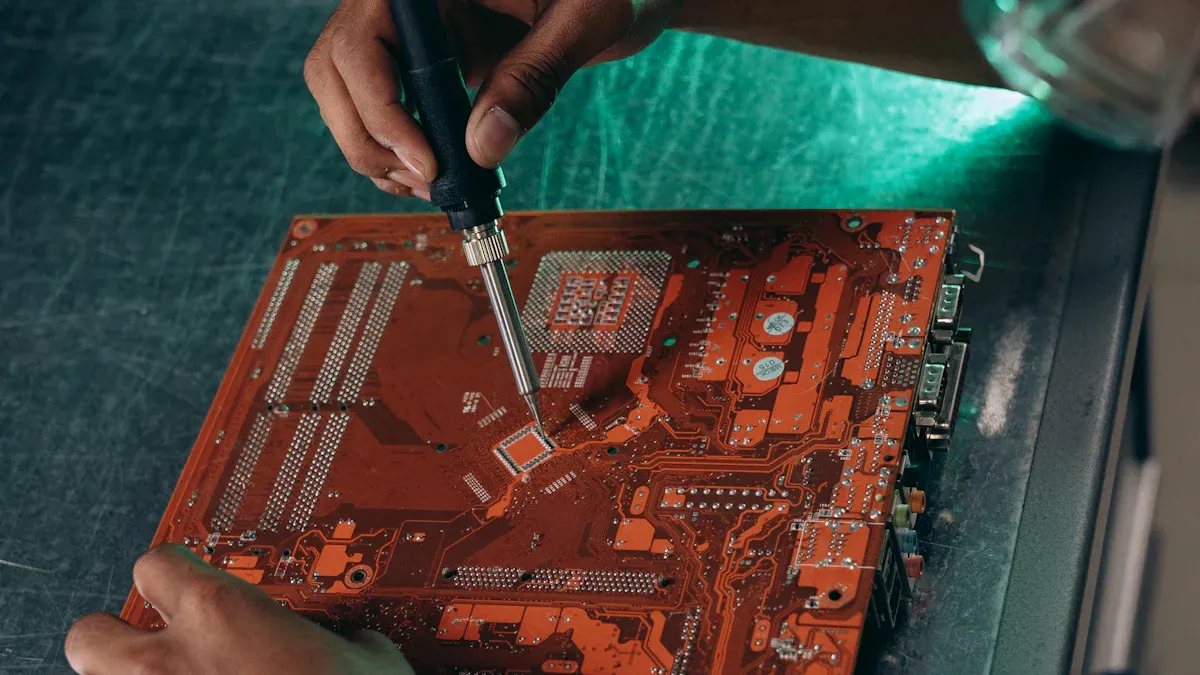
Locate Chip
You need to find the WQFN40 Switch Chip on your Nintendo Switch motherboard before you can remove it. This chip usually sits near the USB-C port or close to the main processor. The WQFN40 Switch Chip has a flat, square shape with no visible pins on the sides. You will see a small marking or dot on one corner. This mark shows you how to align the chip later.
Use a microscope or magnifier to look closely at the motherboard. Check for the chip label printed on the board. The label often matches the part number or has a small outline around the chip. If you are not sure, compare your board to online repair guides or photos. Take your time during this step. Correct identification helps you avoid mistakes and keeps other parts safe.
Tip: Take a clear photo of the chip and its position on the board. This photo will help you when you install the new chip.
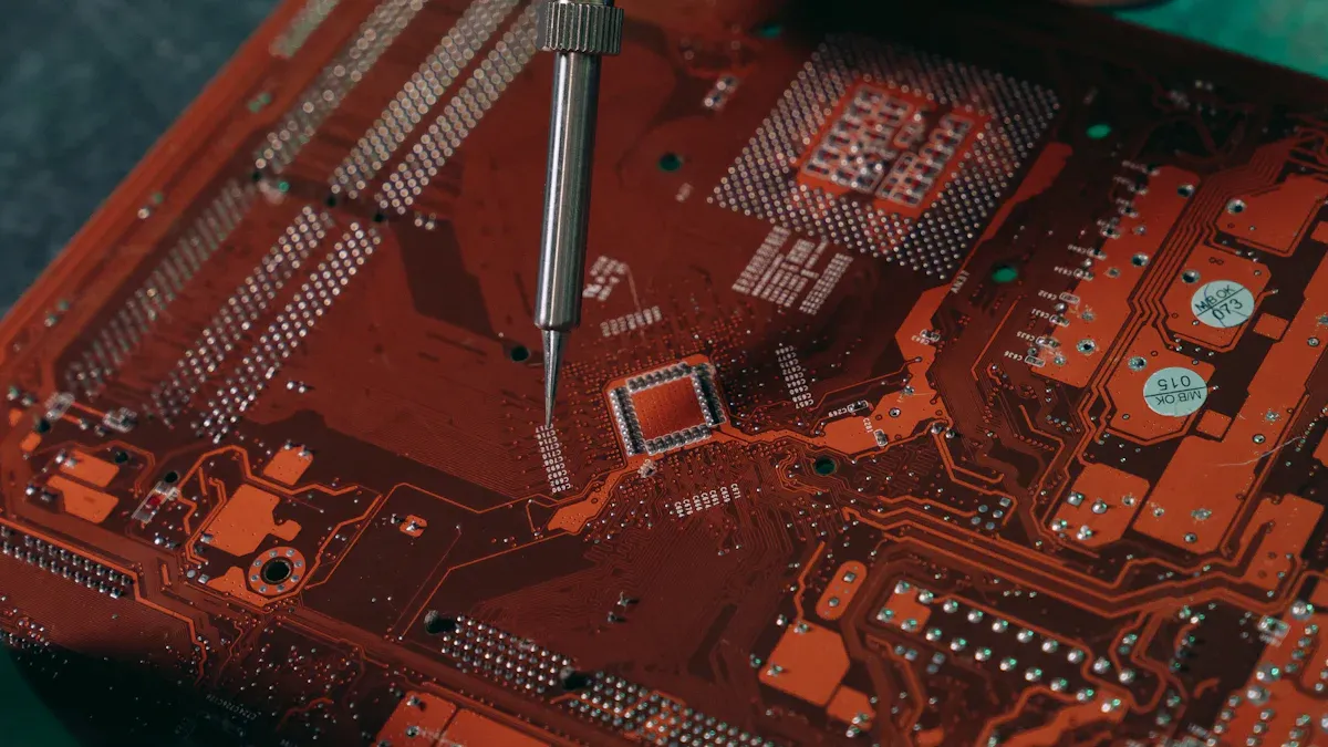
Desolder Chip
You must remove the WQFN40 Switch Chip with care. Start by cleaning the area around the chip with isopropyl alcohol. This step removes dust and old flux. Next, use Kapton tape to cover and protect the small parts near the chip. Kapton tape can handle high heat and keeps nearby capacitors and resistors safe.
Set your hot air rework station to the right temperature. Most chips like the WQFN40 Switch Chip need about 320°C to 350°C. Hold the nozzle a few centimeters above the chip. Move the hot air in small circles over the chip. This method heats the solder evenly and prevents damage.
Hot air rework stations work well for removing surface-mounted chips.
The hot air melts the solder under the chip, so you can lift it off without force.
Kapton tape helps keep the heat focused on the chip and protects other parts.
After about 30 to 60 seconds, use tweezers to gently lift the chip. If it does not move, apply heat for a few more seconds. Do not pry or force the chip. Forcing can damage the motherboard pads. Always keep your hand steady and watch the chip closely.
Note: Too much heat can damage the board or nearby components. Always use the lowest temperature that works and keep the hot air moving.
Once you remove the WQFN40 Switch Chip, let the board cool for a few minutes. Clean the area again with isopropyl alcohol. Check the pads under the chip for any damage. If you see lifted pads or missing traces, you may need extra repair steps before installing the new chip.
Install WQFN40 Switch Chip
Clean Pads
You need to prepare the pad area before you install the new WQFN40 Switch Chip. Start by cleaning the pads with isopropyl alcohol and a lint-free cloth. This step removes old solder, dust, and leftover flux. You should use a desoldering braid to clear away any extra solder. Make sure the pads look shiny and flat.
Apply a small amount of fresh flux to the pads. Flux helps the solder flow and stick to the metal pads. It also prevents oxidation during the soldering process. Many repair experts recommend this step because it makes the new chip installation easier and more reliable. One user shared that cleaning the pad area with 99.9% isopropyl alcohol after removing flux revealed marks on the board. This shows that cleaning can expose hidden issues, so always check the pads for damage before moving forward.
Tip: Always inspect the pads under a microscope. Look for lifted pads or missing traces. If you see any problems, fix them before you continue.
Solder New Chip
You must align the new WQFN40 Switch Chip carefully. Hold the chip with tweezers and match the dot or marking on the chip to the same spot on the board. This ensures the chip sits in the correct orientation. Use a microscope to help you see the small details.
Once you have the chip in place, use your hot air rework station to heat the area. Set the temperature to around 320°C to 350°C. Move the nozzle in small circles above the chip. The solder will melt and the chip will settle onto the pads. You should see the chip "float" slightly when the solder melts. This means the connections are forming.
Let the board cool for a few minutes. Do not move the chip while the solder is still hot. After cooling, inspect the solder joints with your microscope. Look for even, shiny connections around all sides of the chip. If you see any bridges or gaps, use your soldering iron and a small amount of solder to fix them.
Use a small brush and isopropyl alcohol to clean away any leftover flux.
Check the area for any solder splashes or debris.
Make sure the chip sits flat and does not wiggle.
Note: Precision matters. A microscope helps you spot mistakes before they cause problems.
You have now installed the new WQFN40 Switch Chip. Careful cleaning, alignment, and soldering help ensure your Nintendo Switch works as expected.
Reassembly and Testing
Reassemble Console
You have finished installing the new chip. Now, you need to put your Nintendo Switch back together. Start by placing the motherboard into the case. Make sure it sits flat and lines up with the screw holes. Reconnect all ribbon cables and press connectors. Each connector should click into place. Do not force any part. If something does not fit, check the alignment.
Next, attach the speaker wires and antenna cables. Use tweezers for small connectors. Replace the shield plate and secure it with screws. Apply new thermal paste to the processor before installing the heat sink. This step helps keep your console cool. Carefully set the heat sink in place and screw it down.
Put the microSD card reader back and connect it. Place the rear panel on the console. Insert all screws in their original spots. Tighten them gently. Over-tightening can strip the threads or crack the plastic. Reattach the Joy Con controllers.
Repair guides, like those from iFixit, show that careful handling of connectors and thermal paste is important. They also remind you to watch for fragile parts and to keep track of every screw.
Test Functionality
After reassembly, you need to check if your repair worked. Plug in the battery or connect the power supply. Press the power button. The Nintendo Switch should turn on and show the logo. If the screen stays black, check the battery connection and ribbon cables.
Test all buttons, the touchscreen, and the speakers. Insert a game card and see if the console reads it. Try charging the device with the USB-C port. If you see any problems, open the console again and inspect your work. Look for loose connectors, missing screws, or misplaced cables.
Sometimes, a repair does not work on the first try. Forums like TronicsFix explain that success depends on careful inspection and proper soldering. If you still have issues, check for signs of board damage or corrosion. You may need to repeat some steps or seek help from a professional.
Tip: Take your time during testing. Rushing can lead to missed problems or extra work later.
You have learned how to replace a WQFN40 Switch Chip in your Nintendo Switch. Take your time with each step and check your work often. Patience and precision help you avoid mistakes. If you feel unsure, ask a professional for help. Using the right tools and following safety tips keeps your repair safe and successful. Careful DIY repair can save money and teach you new skills.
FAQ
How do I know if my WQFN40 chip is faulty?
You may see symptoms like charging issues, no power, or USB-C port problems. If you have tried other fixes and the problem remains, the chip could be faulty. Use a microscope to check for visible damage.
Can I replace the chip without a hot air rework station?
You should not try this repair without a hot air rework station. The chip needs even heat for safe removal and installation. Using other tools can damage your motherboard.
What should I do if I lift a pad during removal?
Stop and inspect the area. If you lift a pad, you may need to repair the trace with a jumper wire. You can find guides online for pad repair. Do not continue until you fix the damage.
Is it safe to use leaded solder for this repair?
Leaded solder melts at a lower temperature. This helps protect your board from heat damage. Always work in a well-ventilated area and wear safety gear when using leaded solder.
See Also
An Introduction To Low Impedance Switch Chips Explained
A Guide To Control Chips Used In Smart Appliances
How Communication Chips Function And Their Key Features
