Mastering Op Amp Selection Your 2025 Guide
Operational amplifiers in 2025 are more complex and diverse than ever before. You must select the right op amp for optimal circuit performance, reliability, and cost-effectiveness. A systematic approach is crucial. It considers traditional specifications and new technologies. The operational amplifier market shows a Compound Annual Growth Rate of 3.93% from 2025 to 2035. This guide helps you navigate this landscape. For example, selecting a specific part like the OP284ESZ-REEL requires careful consideration.
Key Takeaways
Define your application's needs first. Consider signal type, power limits, and environment. This helps you choose the right op amp.
Understand key op amp parameters. Look at input offset voltage, slew rate, and gain-bandwidth product. These details show how the op amp will perform.
Explore different op amp types. General-purpose, precision, low-power, and high-speed op amps exist. Each type fits specific design needs.
Use a step-by-step selection process. Define critical needs, use manufacturer tools, and check datasheets. Simulate and prototype your circuit to confirm your choice.
Avoid common op amp problems. Watch for headroom issues, noise, and stability problems. Also, consider power use and long-term drift.
Define Application Requirements

Before you select an op amp, you must clearly define your application's needs. This step is crucial. It helps you narrow down the vast number of available options. You should identify three to four critical parameters specific to your project.
Signal Characteristics
First, consider the signals your op amp will handle. What type of signal is it? What are its voltage requirements? For many sensors, controllers, and PLCs, a common analog output is 0-10 V. This range spreads the measured value linearly. Other sensors might use 5V outputs. These allow operation from a lower supply voltage.
You also need to know the signal's frequency response. For audio processing, frequencies vary widely:
Bass frequency: 20 Hz - 250 Hz. Bass speakers process this range. It creates strong bass effects for music and low-frequency movie effects.
Middle range frequency: 250 Hz - 2000 Hz. This range includes human speech. It is central to most instrument sounds, including vocals.
High pitch frequency: 2000 Hz - 20000 Hz. This range covers high-pitched sounds you can hear. It includes instruments like violins and sharp vocal tones.
Finally, think about noise characteristics. How much noise can your system tolerate?
Power Constraints
Next, evaluate your power budget. What is your available supply voltage? How much power can your circuit consume? For battery-powered IoT devices, current consumption can range from tens of nanoamps to hundreds of milliamps. Battery life can vary from days to 20-30 years. While specific limits are not always given, understanding these ranges helps you choose efficient op amps.
Environmental Factors
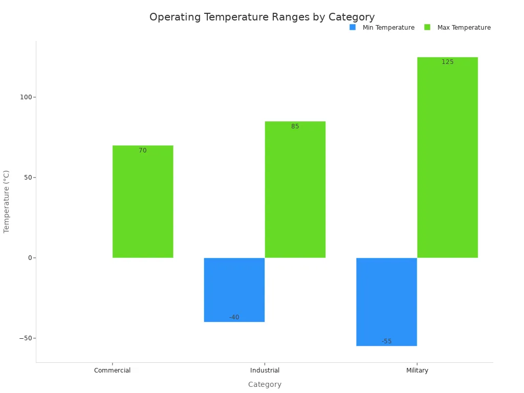
Your op amp must work reliably in its environment. Consider the operating temperature range. Industrial control systems often face harsh conditions.
Category | Temperature Range |
|---|---|
Commercial | 0 to 70 °C |
Industrial | -40 to 85 °C |
Military | -55 to 125 °C |
Most electrical components are rated from -40°C up to 85°C. For best performance, keep temperatures inside electrical cabinets below 40°C (104°F). Many devices can handle up to 50°C (122°F).
Also, think about humidity, vibration, and electromagnetic interference. These factors can affect op amp performance.
Cost and Availability
Finally, consider your project budget. How much can you spend on each op amp? Also, check the availability of the chosen part. Ensure you can source it reliably for your production needs.
Key Op Amp Parameters
You must understand several key parameters when you select an op amp. These parameters tell you how the op amp will perform in your circuit. They help you match the op amp to your application's specific needs.
Input Characteristics
The input characteristics describe how the op amp interacts with the signal you feed into it.
Input Offset Voltage (Vos): This is a small voltage difference you need to apply between the input terminals to make the output zero. Ideally, it should be zero. A lower Vos means higher precision. Precision op amps typically have an input offset voltage (Vos) of less than 1mV. You can find them further classified by offset voltage into ranges such as ≤10 µV, 10 to 25 µV, 25 to 150 µV, and >150 µV.
Input Bias Current (Ib): A tiny current flows into or out of the input terminals. You want this current to be as small as possible, especially when you use high-impedance sources.
Input Impedance: This tells you how much the op amp "loads" your input signal. A high input impedance means the op amp draws very little current from your signal source. This prevents the op amp from affecting the signal itself.
Output Characteristics
Output characteristics tell you what the op amp can deliver to your load.
Output Voltage Swing: This is the maximum voltage range the op amp can produce at its output. You need to ensure it covers the full range of your required output signal.
Output Current Drive: This specifies how much current the op amp can supply to a load. Output current values for op-amps are frequently quite low. They often fall in the single-digit mA range or between 10-20 mA at most. A general-purpose op-amp should have at least 20mA of output current when powered at 5V. This helps it drive simple RC low-frequency filters and buffered outputs. For example, the OPA994-Q1 is an automotive, single-channel, 32V, 25MHz operational amplifier. Its high-output current of 150 mA is a specific feature, not a typical general-purpose capability.
Slew Rate: This is how fast the output voltage can change. It measures the maximum rate of change of the output voltage over time. If your signal changes quickly, you need an op amp with a high slew rate to avoid distortion. Special high-speed operational amplifiers can achieve slew rates in the range of several thousand volts per microsecond.
Device | Slew Rate |
|---|---|
LM6364 | 300 V/µs |
LT1363 | 1000 V/µs |
Gain and Stability
Gain and stability are crucial for how your op amp amplifies signals without unwanted oscillations.
Open-Loop Gain (Aol): This is the gain of the op amp without any feedback. It is usually very high, often hundreds of thousands or millions.
Gain-Bandwidth Product (GBW or fGBWP): This is a crucial AC parameter for op-amp selection. It tells you the frequency at which the op amp's open-loop gain drops to one (unity). It also indicates the maximum frequency you can amplify for a given gain. For example, a typical op amp has a GBW of 1 MHz. A 741 op amp typically has a GBW of 1 MHz. An LF411 op amp typically has an f_unity of 4 MHz.
Stability: An op amp circuit can become unstable and oscillate if you do not design it correctly. You must ensure your op amp circuit remains stable. You can use common methods to ensure op amp stability in feedback circuits:
Isolation resistor compensation: You use this when the feedback loop has a reactive component, like in low-pass filtering with gain. Adding an isolation resistor changes the loop gain transfer function. It either dampens the output before it reaches a capacitive load or sets a zero in the transfer function at the point of instability.
Dominant pole compensation: This involves intentionally adding a pole into the open-loop transfer function. You typically do this by placing a low-pass filter circuit between the output and the load. This causes an early rolloff in the open-loop gain curve. It severely reduces oscillations near the instability point. The new dominant pole frequency should be less than the lowest-order frequency.
Gain compensation: This is a simple method for uncompensated op-amps. You reduce the gain by adjusting feedback resistor values. This increases the frequency limit for instability. It leads to more stable operation, even with lower gain. This is especially true when the device has very high open-loop gain and a high closed-loop gain could trigger instability.
PSRR and CMRR
These parameters describe how well the op amp rejects unwanted signals.
Power Supply Rejection Ratio (PSRR): This tells you how much the output voltage changes when the power supply voltage changes. A high PSRR means the op amp is less sensitive to noise or variations on its power supply lines. You want a high PSRR for stable operation.
Common-Mode Rejection Ratio (CMRR): This measures the op amp's ability to reject common-mode signals. A common-mode signal appears equally on both input terminals. A high CMRR means the op amp effectively ignores these unwanted signals. Instrumentation amplifiers generally show excellent Common-Mode Rejection Ratio (CMRR) performance. For the LT1167 instrumentation amplifier, at a gain of 10, the typical CMRR is 115 dB. At a gain of 1000, the typical CMRR can be as high as 140 dB.
💡 Tip: Always check the datasheet for these key parameters. They help you compare different op amps and choose the best one for your design.
Op Amp Architectures in 2025
You will find many different op amp architectures today. Each type suits specific design needs. Understanding these differences helps you choose the best device for your circuit.
General-Purpose vs. Precision Types
General-purpose op amps are versatile. They work well in many common applications. They offer a good balance of performance and cost. Precision op amps, however, focus on accuracy. They have very low input offset voltage and drift. You use them for critical tasks. These include linear precision current supplies or precise power supplies. They offer low noise and excellent buffering capabilities.
Low-Power vs. High-Speed Options
Low-power op amps save energy. They are perfect for battery-powered devices. They often have lower bandwidth. High-speed op amps handle fast signals. They offer wide bandwidth and high slew rates. You use them in video systems or RF applications. They typically consume more power.
Zero-Drift (Chopper) Amplifiers
Zero-drift amplifiers offer extremely low input offset voltage and drift over time and temperature. They achieve this precision through special techniques.
Auto-zero amplifiers use a correction amplifier. This amplifier measures the main amplifier's input offset voltage. It stores this data in a capacitor. Then, it uses this data to remove the main amplifier's input offset voltage. This minimizes the offset.
Chopper amplifiers convert the input signal to an AC signal. An input modulation circuit does this. The op amp amplifies this AC signal. Then, it converts it back to a DC signal. The input offset voltage bypasses the input modulation circuit. It becomes an AC signal in the output demodulation circuit. A low-pass filter then removes this AC offset voltage. This minimizes the input offset voltage.
Current-Feedback vs. Voltage-Feedback
Voltage-feedback op amps are common. They have high input impedance and low output impedance. They work well in many applications. Current-feedback op amps offer higher bandwidth. Their bandwidth stays more constant with gain changes. You use them in high-speed applications.
Emerging Trends and Integrated Features
Modern op amps offer more than just basic amplification. They include many integrated features.
Rail-to-rail output lets the output signal span from the lowest to the highest supply voltage.
Rail-to-rail inputs allow operation with input signals very close to the power supply rails.
CMOS op amps, like the CA3140E, offer extremely high input resistances. These surpass JFET-input and bipolar-input op amps.
Some op amps are programmable. You can adjust their quiescent current and bandwidth with an external resistor.
You can also find op amps with programmable gain. You adjust this externally via SPI.
Many offer high bandwidth, even up to 2.4 GHz.
You can find multiple channels, such as 8-channel devices.
They often include integrated power management modes.
Inverting and Non-Inverting Configurations
You will often use op amps in either inverting or non-inverting configurations. Each has distinct characteristics.
Inverting configuration: The output signal is 180 degrees out of phase with the input. It offers precise gain control.
Non-inverting configuration: The output signal is in phase with the input. It provides high input impedance. For a non-inverting op-amp, the voltage gain (Av) is Av = Vout/Vin = (R1+R2)/R2. This means the resistor ratio determines the gain.
Consider gain, bandwidth, noise, stability, and layout when choosing between these configurations.
Op Amp Selection Process
Choosing the right op amp involves a careful, step-by-step process. You start by clearly defining your needs. Then, you use available tools to find the best match. Finally, you test your choice.
Critical Specification Definition
You must first identify the absolute "must-have" features for your op amp. These are the specifications your circuit cannot work without. For example, if you are designing a high-precision data acquisition system, several specifications become critical.
Input Offset Voltage (Vos): This is a major source of error. Even a tiny offset can cause constant errors in your analog-to-digital converter (ADC) output. This is especially true in systems that handle DC signals. Precision op amps aim for Vos below 1 millivolt (mV). For very high accuracy, like with 24-bit ADCs, you might need special compensation. A 500 microvolt (µV) offset can shift readings by several least significant bits (LSBs).
Settling Time: This tells you how fast the op amp's output becomes stable after a sudden input change. For fast ADCs, the op amp must settle very quickly. It needs to be within 0.5 LSB of the final value before the ADC takes a sample. For a 16-bit ADC with a 5V reference, 1 LSB is about 76 µV. You need an op amp with a settling time faster than the ADC's sampling window. For example, a 1 MSPS ADC might need settling to 0.01% accuracy in 100 nanoseconds (ns).
Slew Rate: This ensures the op amp can handle quick signal changes without errors. A slew rate of at least 10 V/µs is important. This applies to applications like audio processing or fast sensor measurements.
Output Current Capability & Low Output Impedance: These are vital for driving high-resolution ADCs. Many ADCs have switched-capacitor inputs. These inputs draw quick, temporary currents. The op amp must supply this current fast. This prevents the input voltage from dropping and causing errors. You need high output current, often 20 mA or more, and low output impedance.
Low Drift & High Common-Mode Rejection Ratio (CMRR): For applications like strain gauges, you amplify very small signals. The amplifier must have low drift. It also needs a high CMRR, at least 100 dB. This helps reject interference from power lines or motors.
Linearity (Low Total Harmonic Distortion - THD): Nonlinearity creates harmonic distortion. High-resolution ADCs will digitize this distortion. This leads to incorrect data. Op amps with THD below -100 dB give the best results.
Secondary Specification Prioritization
After defining your critical specifications, you prioritize secondary ones. These are important but might have some flexibility. For example, you might prefer a low-power op amp. However, if it cannot meet your speed requirements, speed becomes more important. You often make trade-offs here. You might choose a slightly higher power consumption for better noise performance. Or, you might accept a slightly larger package size for a lower cost.
Manufacturer Tools and Parametric Search
Once you know your key requirements, you can use manufacturer tools. These online tools help you search through thousands of op amps. They act like a digital catalog with powerful filters. You can narrow down your choices quickly.
These tools offer many ways to filter devices:
Input Type: You can choose between Bipolar-input op amps or FET/CMOS op amps.
Features: You can look for specific traits. These include low power (less than 1 mA per channel), low noise (less than 1.7 nV/√Hz), high output current (more than 200 mA), or high precision (VOS less than 500 µV).
Size: You can filter by the number of channels and package size. Options include single channel (less than 5 mm²), dual channel (less than 8 mm²), quad channel (less than 12 mm²), and even bare die (less than 1.1 mm²).
Part Ratings: You can filter for devices rated for automotive, space, high reliability, or functional safety.
Special Functions: Some op amps have unique roles. You can search for high-speed buffers, high-speed transimpedance amplifiers, high-power line drivers, differential ADC drivers, or programmable/variable gain amplifiers.
Datasheet Evaluation (e.g., OP284ESZ-REEL)
After using parametric search, you will have a shortlist of potential op amps. Now, you must dive into their datasheets. The datasheet is the most important document for understanding an op amp's true performance. For example, let's consider the OP284ESZ-REEL. You would open its datasheet to find detailed information.
Look for the "Electrical Characteristics" table. Here, you will find values for input offset voltage, input bias current, slew rate, and gain-bandwidth product. For the OP284ESZ-REEL, you would check its Vos to ensure it meets your precision needs. You also examine graphs. These graphs show how parameters change with temperature or frequency. For instance, the OP284ESZ-REEL datasheet will have plots for open-loop gain versus frequency. This helps you understand its stability. You should also look at the "Typical Application Circuits" section. These examples show how to use the OP284ESZ-REEL in common configurations. They can give you ideas for your own design. Pay attention to power supply requirements and recommended external components for the OP284ESZ-REEL.
Simulation and Prototyping
Before you build your circuit, simulate it. Simulation saves time and money. It helps you catch potential problems early. You can test your op amp choice in a virtual environment.
Several tools help you simulate op amp circuits:
CircuitLab: This is an online tool. You use it in your web browser. It lets you draw schematics and simulate circuits. CircuitLab can simulate op amp circuits in DC, time, and frequency domains. It offers two op amp models. One includes voltage rails, and one does not. The simpler model simulates faster if you do not worry about output limits.
TINA-TI: This tool is from Texas Instruments. It helps you simulate complex analog power and signal-chain circuits. You can use TINA-TI to analyze how your chosen op amp will behave in your specific circuit.
After successful simulation, you move to prototyping. Build a physical version of your circuit. Test it thoroughly. This final step confirms your op amp selection works as expected in the real world.
Common Op Amp Pitfalls
Even with careful selection, you can encounter common issues. You must know these pitfalls. This helps you avoid problems in your circuit design.
Input/Output Headroom Issues
You must understand input/output headroom. This refers to the voltage space between your signal and the power supply rails. Many op amps cannot swing their output all the way to the supply rails. If your signal tries to go beyond these limits, the op amp will clip or saturate. This distorts your output signal. Always check the datasheet for the specified output voltage swing. Choose rail-to-rail op amps if your application needs the full voltage range.
Underestimated Noise Requirements
Every op amp adds some noise to your signal. You might underestimate how much noise your circuit can tolerate. This noise can hide small signals you want to amplify. You need to consider thermal noise, flicker noise, and shot noise. For precision applications, you must calculate the total noise. Compare this noise level to your smallest signal. Select low-noise op amps for sensitive measurements. 🤫
Stability Problems
Op amps can become unstable. They might oscillate instead of amplifying your signal cleanly. This often happens with capacitive loads or complex feedback networks. Insufficient phase margin is a common cause. Oscillations lead to distorted outputs or complete circuit failure. You must ensure your op amp circuit remains stable.
💡 Tip: You can use compensation techniques. These include isolation resistors or dominant pole compensation. They help prevent unwanted oscillations.
Overlooked Power Dissipation
Op amps consume power. This power turns into heat. If you overlook power dissipation, your op amp can overheat. Excessive heat reduces the op amp's lifespan. It can also lead to thermal runaway. Always calculate the power your op amp will dissipate. Consider the package type and if you need a heatsink. This prevents thermal issues.
Long-Term Drift and Temperature Effects
Op amp parameters change over time and with temperature. This is called drift. Input offset voltage drift is a common issue. Gain can also drift. These changes affect the accuracy of your precision circuits. For critical applications, you need to account for these effects. Consider using zero-drift (chopper) amplifiers. You might also implement temperature compensation.
Successful op amp selection in 2025 combines foundational knowledge with new technology. You need a systematic approach. Start with application requirements. Then evaluate parameters. Choose the right architecture. Finally, verify your choice. Careful selection leads to robust, efficient, and reliable circuit designs. Keep learning about new op amp technologies. Use updated selection guides. They help you choose the best device.
FAQ
What is the most critical op amp parameter?
No single parameter is most critical. Your application defines the most important ones. For precision, focus on input offset voltage. For speed, look at slew rate and bandwidth. Always match the op amp to your specific circuit needs. You must prioritize based on your design.
Why do some op amps have "rail-to-rail" features?
Rail-to-rail features allow the op amp's input or output to operate very close to the power supply voltages. This maximizes the dynamic range. It is crucial for low-voltage or battery-powered applications. It prevents signal clipping. You get the full voltage range.
How can I prevent my op amp circuit from oscillating?
Op amp circuits can oscillate if you do not design them correctly. You can use compensation techniques. Add isolation resistors. Implement dominant pole compensation. These methods improve stability. Always check the datasheet for stability guidelines. 💡
What is the purpose of the Gain-Bandwidth Product (GBW)?
The Gain-Bandwidth Product (GBW) tells you an op amp's speed. It indicates the frequency where the open-loop gain drops to one. You use it to determine the maximum frequency you can amplify for a given gain. A higher GBW means faster operation.
See Also
Essential MOSFET Fundamentals: A Guide for Electronics Hobbyists
Crafting High-Fidelity Audio Amplifiers: A 2025 Design and Build Guide
Leading Synchronous Buck Converter Chips: Our Top Three Selections for 2025
Analog Integrated Circuit Design: Core Principles and Practical Uses Explained
Selecting the Ideal SOT23-6 Buck Regulator Chip: A Comprehensive Buyer's Guide
