How to Fix a Faulty Rectifier IC in Your Induction Cooker
A faulty rectifier IC can disrupt your induction cooker's performance, leaving you unable to prepare meals efficiently. You can spot the issue by paying attention to signs like inconsistent heating or error codes on the display. Fixing the problem promptly keeps your appliance running smoothly and prevents further damage. By learning how to diagnose and repair the Induction Cooker Rectifier IC, you can save time and avoid costly replacements.
Key Takeaways
Look for signs of a bad rectifier IC, like error messages, uneven heating, or strange sounds. Spotting these early can stop more damage.
Check the rectifier IC and other parts with a multimeter. Correct testing shows if the IC works right.
Stay safe by unplugging the cooker and wearing safety gear before fixing it. This helps avoid shocks or getting hurt.
Clean the circuit board and use a surge protector often. This can stop problems from happening later.
If fixing it feels too hard, ask a repair expert. A pro can make sure your cooker gets fixed the right way.
Symptoms of a Faulty Induction Cooker Rectifier IC
Induction cooker not powering on
When your induction cooker refuses to power on, the rectifier IC might be the culprit. This component plays a critical role in converting AC power to DC, which is essential for the appliance's operation. A common technical issue involves the absence of the +5V voltage output. Even if the +300V and +18V voltages are normal, the failure of the 7805 voltage regulator can prevent the control circuit from receiving the necessary +5V. Without this voltage, the induction cooker remains unresponsive.
If you encounter this issue, start by checking the power supply and ensuring the socket is functional. Once you rule out external factors, focus on the internal components, particularly the rectifier IC.
Error codes or warning lights on the display
Modern induction cookers often display error codes or warning lights when something goes wrong. These indicators can point to a faulty rectifier IC. For example, if the IC fails to regulate voltage properly, the control board may detect irregularities and trigger an error message.
Pay close attention to the specific code or light pattern. Refer to your induction cooker's manual to interpret these signals. They can guide you toward identifying whether the rectifier IC or another component is at fault.
Unusual noises or burning smells
A faulty rectifier IC can cause unusual noises, such as buzzing or humming, during operation. These sounds often result from electrical irregularities within the circuit. In more severe cases, you might notice a burning smell, which could indicate overheating or damage to the IC or nearby components.
If you detect these signs, turn off the induction cooker immediately and disconnect it from the power source. Continuing to use the appliance in this state can lead to further damage or even pose safety risks. Inspect the rectifier IC and surrounding parts for visible signs of damage, such as burn marks or melted components.
Inconsistent heating or failure to heat
Inconsistent heating or a complete failure to heat is another common symptom of a faulty Induction Cooker Rectifier IC. You might notice that your induction cooker heats unevenly or stops heating altogether during use. This issue often stems from the rectifier IC's inability to supply stable DC voltage to the control circuit. Without consistent voltage, the induction coil cannot generate the electromagnetic field required for heating.
To address this problem, start by observing the heating pattern. If the cooker heats intermittently, it could indicate voltage fluctuations caused by the rectifier IC. On the other hand, if the cooker fails to heat entirely, the IC may have stopped functioning.
Steps to Investigate Heating Issues
Inspect the cookware compatibility: Ensure your cookware is induction-compatible. Non-compatible cookware can mimic heating issues.
Check the power supply: Verify that the power outlet provides stable voltage. Unstable power can affect the rectifier IC's performance.
Examine the circuit board: Open the induction cooker and inspect the rectifier IC for visible damage. Look for burn marks or swollen components.
Test the rectifier IC: Use a multimeter to measure the voltage output of the IC. Compare the readings to the specifications in your induction cooker's manual.
Tip: If you find irregular voltage readings, replace the rectifier IC immediately to prevent further damage to the appliance.
Preventive Measures
To avoid future heating problems, maintain your induction cooker regularly. Clean the circuit board to remove dust and debris that can interfere with electrical components. Use a surge protector to shield the rectifier IC from power fluctuations.
By addressing inconsistent heating promptly, you can restore your induction cooker's functionality and extend its lifespan.
Diagnosing a Faulty Induction Cooker Rectifier IC
Safety precautions before starting
Before diagnosing your induction cooker, prioritize safety to avoid injuries or damage to the appliance. Always unplug the cooker and discharge all capacitors to eliminate the risk of electric shock. Use protective gear, including safety glasses, gloves, and a mask, to shield yourself from debris or chemicals during the inspection. Ground your workstation and use an ESD-safe mat to prevent electrostatic discharge, which can damage sensitive components.
Tip: Double-check that the appliance is completely disconnected from the power source before proceeding.
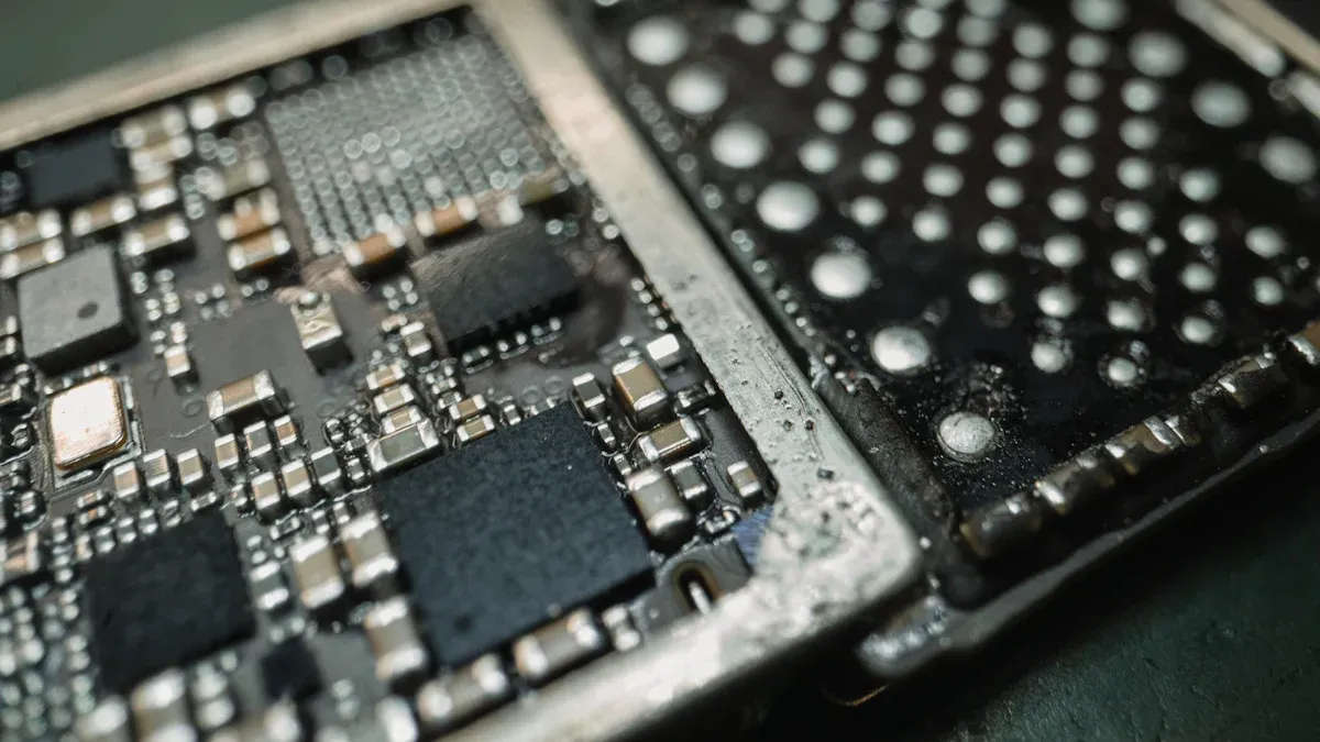
Visual inspection of the rectifier IC and surrounding components
A thorough visual inspection can reveal obvious signs of damage to the rectifier IC and nearby parts. Look for cracks, discoloration, or burn marks on the IC. Check the solder joints to ensure they are secure and free from corrosion. Examine the circuit board for inappropriate connections or overheated components, which may appear burnt or bulged.
Here’s a checklist to guide your inspection:
Inspect the diode for cracks, discoloration, or burn marks.
Check solder joints for looseness or corrosion.
Look for bulged or dull components on the PCB.
Identify any burnt marks on the circuit board or mounting points.
If you notice any of these issues, the rectifier IC or related components may need replacement.
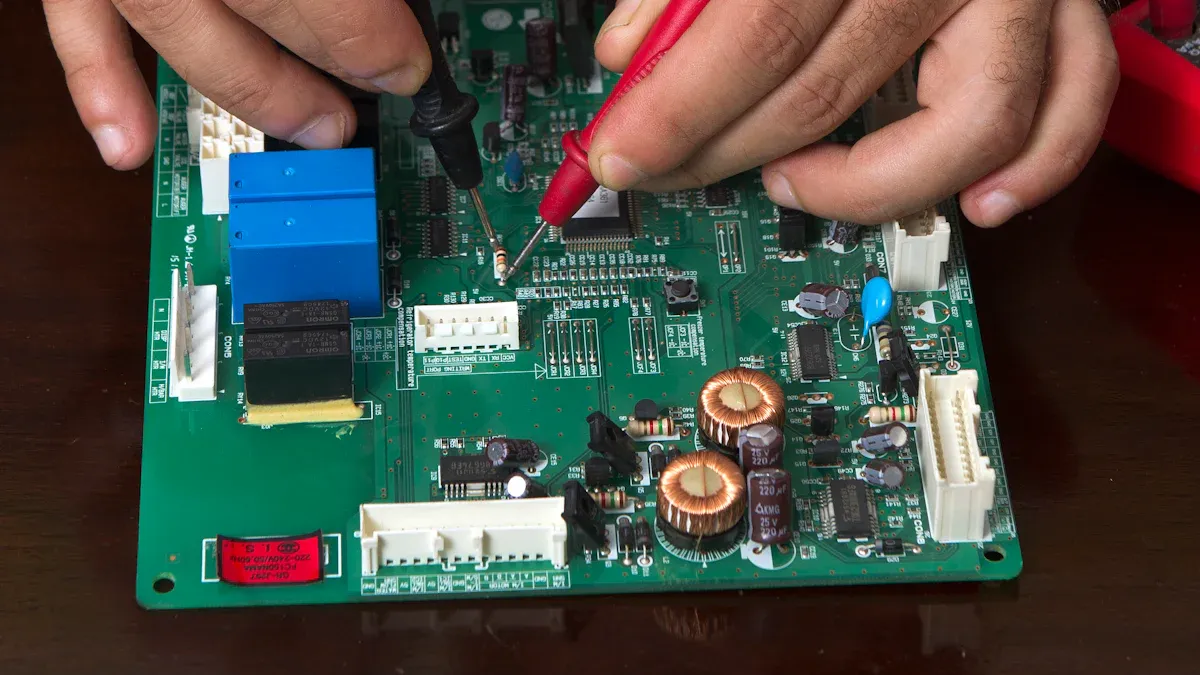
Using a multimeter to test the rectifier IC
Testing the rectifier IC with a multimeter helps confirm whether it is functioning correctly. Set the multimeter to the diode testing mode. Place the probes on the IC terminals as specified in your induction cooker’s manual. A functioning rectifier IC will show consistent readings within the expected range.
For a more advanced diagnosis, you can use methods like current space vector trajectory or spectrum analysis. These techniques analyze current patterns and frequency spectrums to detect faults. The table below summarizes some effective diagnostic methods:
Diagnostic Method | Description |
|---|---|
Average currents method | Analyzes average line currents to identify faults in uncontrolled three-phase rectifiers. |
Current space vector trajectory | Utilizes the current Park's vector approach for fault diagnosis in rectifier ICs. |
Spectrum analysis | Examines the frequency spectrum of currents to detect anomalies indicative of faults. |
Analytic redundancy approach | Used for buck converters, based on residues calculation to identify faults. |
Average voltages analysis | A method for series resonant inverters that detects and locates faults in power switches. |
Note: If the multimeter readings or advanced diagnostic results indicate irregularities, replace the rectifier IC promptly to restore your induction cooker’s functionality.
Checking related components like the IGBT and capacitors
When diagnosing a faulty Induction Cooker Rectifier IC, you should also inspect related components like the IGBT (Insulated Gate Bipolar Transistor) and capacitors. These parts often work closely with the rectifier IC, and their failure can cause similar symptoms.
Inspecting the IGBT
The IGBT plays a critical role in controlling the power flow to the induction coil. A damaged IGBT can lead to inconsistent heating or prevent the cooker from functioning altogether. Start by visually examining the IGBT for signs of damage, such as cracks, burn marks, or discoloration. If the component looks intact, use a multimeter to test it. Set the multimeter to the diode mode and check the terminals for proper conductivity. A faulty IGBT may show irregular readings or no continuity at all.
Tip: Always handle the IGBT carefully, as it is sensitive to static electricity. Use an anti-static wrist strap to avoid accidental damage.
Checking the Capacitors
Capacitors store and release electrical energy, helping to stabilize the voltage in the circuit. Faulty capacitors can cause voltage fluctuations, which may affect the performance of the rectifier IC. Look for physical signs of damage, such as bulging, leaking, or burnt areas. To test a capacitor, set your multimeter to the capacitance mode and compare the readings to the specifications in your induction cooker’s manual. Replace any capacitor that shows a significant deviation from the expected value.
Why This Matters
Neglecting to check the IGBT and capacitors can lead to incomplete repairs. These components often fail alongside the rectifier IC, so addressing them ensures your induction cooker operates reliably. By thoroughly inspecting and testing these parts, you can identify and resolve hidden issues that might otherwise go unnoticed.
Tools and Materials for Repairing an Induction Cooker Rectifier IC
Essential tools
You need the right tools to repair your induction cooker effectively. A multimeter is essential for testing the rectifier IC and other components. It helps you measure voltage and identify faults. A soldering iron allows you to remove and replace the faulty IC securely. Choose one with adjustable temperature settings for better control. A screwdriver set is necessary to open the induction cooker and access the circuit board. Ensure the set includes various sizes to match the screws on your appliance.
Tip: Keep a pair of tweezers handy for handling small components on the circuit board.
Replacement rectifier IC and other components
Replacing the faulty rectifier IC is crucial to restoring your induction cooker’s functionality. Purchase a replacement IC that matches the specifications in your appliance’s manual. Using an incompatible IC can cause further damage. You may also need additional components like capacitors or diodes if they show signs of wear or failure during inspection.
When buying replacement parts, choose high-quality components from reputable suppliers. This ensures durability and reliable performance. If you’re unsure about the specifications, consult the manufacturer or a professional technician for guidance.
Safety gear
Safety should always come first when repairing electrical appliances. Wear insulated gloves to protect your hands from electric shocks. Safety goggles shield your eyes from soldering fumes and debris. A mask prevents you from inhaling harmful particles during the repair process.
Note: Use an anti-static wrist strap to avoid damaging sensitive components with static electricity.
By gathering these tools, materials, and safety gear, you’ll be well-prepared to repair your induction cooker rectifier IC confidently and safely.
Step-by-Step Guide to Replacing a Faulty Induction Cooker Rectifier IC
Disconnecting the induction cooker from power
Before starting any repair work, you must disconnect the induction cooker from its power source. This step is crucial for your safety and prevents accidental electric shocks. Unplug the appliance from the wall socket and ensure no residual power remains in the circuit.
To discharge any stored electricity, press and hold the power button for about 10 seconds after unplugging the cooker. This action helps release any remaining charge in the capacitors. If your induction cooker has a detachable power cord, remove it completely to avoid accidental reconnection during the repair process.
Safety Tip: Always double-check that the appliance is completely disconnected from power before proceeding. Never skip this step, as working on a live circuit can be dangerous.
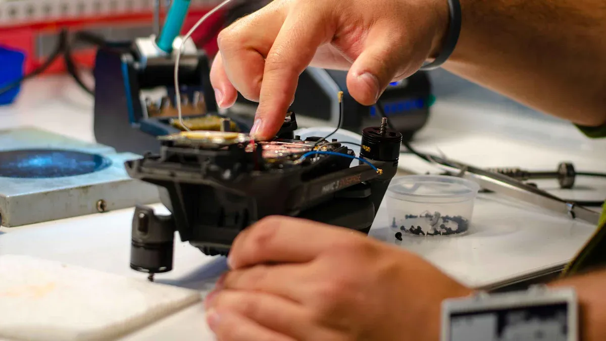
Accessing the circuit board
Once the induction cooker is safely disconnected, you can access the circuit board where the rectifier IC is located. Start by placing the appliance on a flat, stable surface. Use a screwdriver to remove the screws securing the outer casing. Keep the screws in a small container to avoid losing them.
Carefully lift the casing to expose the internal components. You will see the circuit board, which houses the rectifier IC and other parts like capacitors and the IGBT. Take a moment to familiarize yourself with the layout. Refer to your induction cooker’s manual if you have trouble identifying the rectifier IC.
Pro Tip: Take a photo of the circuit board before proceeding. This will help you remember the original placement of components and wires during reassembly.
Removing the faulty rectifier IC
To remove the faulty rectifier IC, you need a soldering iron and some desoldering tools. Begin by locating the IC on the circuit board. It is usually a small, rectangular component with several pins soldered to the board.
Heat the soldering iron to the recommended temperature (usually around 350°C or 662°F). Use the tip of the iron to melt the solder on each pin of the rectifier IC. As the solder melts, use a desoldering pump or wick to remove it. Work carefully to avoid damaging the surrounding components or the circuit board itself.
Once all the pins are free of solder, gently lift the rectifier IC from the board using tweezers. If the IC does not come off easily, check for any remaining solder and remove it before trying again.
Important: Avoid applying excessive heat to the circuit board, as this can damage the traces and make reassembly more difficult.
After removing the faulty rectifier IC, inspect the area for any leftover solder or debris. Clean the solder pads with isopropyl alcohol and a cotton swab to prepare the board for the installation of the new IC.
Installing the new rectifier IC
After removing the faulty rectifier IC, you can install the new one to restore your induction cooker's functionality. Follow these steps to ensure a proper installation:
Position the new rectifier IC: Align the pins of the new IC with the corresponding holes on the circuit board. Make sure the orientation matches the markings on the board. Incorrect placement can damage the component or the appliance.
Secure the IC in place: Hold the IC steady while inserting the pins into the holes. Ensure the component sits flush against the board without tilting.
Solder the pins: Heat your soldering iron to the recommended temperature. Apply a small amount of solder to each pin, creating a secure connection between the IC and the board. Avoid using too much solder, as it can create bridges between pins and cause short circuits.
Inspect your work: Check each solder joint to ensure it is clean and solid. Look for any excess solder or weak connections. If necessary, reheat and adjust the joints for better contact.
Tip: Use a magnifying glass to inspect the solder joints closely. This helps you spot any imperfections that might affect the IC's performance.
Once the new rectifier IC is installed, clean the area with isopropyl alcohol to remove any flux residue. This step prevents corrosion and ensures a long-lasting repair.
Reassembling and testing the induction cooker
With the new rectifier IC in place, you can reassemble the induction cooker and test its functionality. Here's how to proceed:
Reattach the casing: Place the outer casing back onto the appliance. Align it carefully to avoid pinching any wires or components. Secure it with the screws you removed earlier. Tighten the screws evenly to ensure the casing fits snugly.
Reconnect the power cord: Plug the power cord back into the induction cooker. Double-check that all connections are secure before proceeding.
Test the appliance: Plug the induction cooker into a power outlet and turn it on. Observe the display for any error codes or warning lights. If the appliance powers on and operates normally, the repair was successful.
Check the heating performance: Place a compatible pot on the induction cooker and test its heating capabilities. Ensure the appliance heats evenly and maintains a consistent temperature.
Safety Note: If the induction cooker shows any signs of malfunction, such as unusual noises or error codes, disconnect it immediately. Reinspect the rectifier IC and other components for potential issues.
By carefully reassembling and testing your induction cooker, you can confirm that the new rectifier IC is functioning correctly. This process ensures your appliance is ready for regular use.
Fixing a faulty rectifier IC in your induction cooker involves diagnosing the issue, gathering the right tools, and following a step-by-step repair process. You start by identifying symptoms like error codes or inconsistent heating. Then, you inspect and test the rectifier IC and related components. Finally, you replace the faulty IC and test the appliance to ensure proper functionality.
Reminder: Always prioritize safety. Wear protective gear and disconnect the appliance from power before starting repairs.
With patience and the right approach, you can restore your induction cooker. If the task feels overwhelming, consult a professional technician for assistance.
FAQ
What is a rectifier IC, and why is it important in an induction cooker?
A rectifier IC converts AC power to DC, which powers the induction cooker's control circuit. Without it, the appliance cannot function properly. It ensures stable voltage for consistent heating and smooth operation.
How can I tell if my rectifier IC is faulty?
Look for symptoms like error codes, inconsistent heating, or the cooker not powering on. You might also notice unusual noises or burning smells. Testing with a multimeter confirms if the IC is defective.
Can I repair a faulty rectifier IC without professional help?
Yes, you can repair it if you have the right tools and follow safety precautions. Use a step-by-step guide to replace the IC. If unsure, consult a technician to avoid further damage.
What tools do I need to replace a rectifier IC?
You’ll need a multimeter, soldering iron, screwdrivers, and safety gear like gloves and goggles. A replacement rectifier IC and possibly other components, like capacitors, are also necessary.
How can I prevent future issues with my induction cooker?
Regular maintenance helps. Clean the circuit board to remove dust. Use a surge protector to shield the rectifier IC from power fluctuations. Address minor issues promptly to avoid major repairs.
Tip: Always unplug your induction cooker before performing any maintenance or repairs. Safety first!
See Also
Steps to Set Up and Program a 555 Timer IC
Understanding IC Line Drivers and Their Function in Electronics
Utilizing Schottky Barrier Power Rectifiers in Electronic Circuits
Defining IC Demodulators and Their Importance in Electronics
