What Is a Current-Loop Transmitter Chip and How Does It Work
A Current-Loop Transmitter chip helps you turn a sensor reading, such as temperature or pressure, into a steady electric current. You often see this chip in action with the 4-20 mA current loop, a standard in factories and plants. This approach lets you send reliable signals over long distances, even in noisy environments. You do not need to worry about voltage drops, so your data stays accurate.
Tip: Using current instead of voltage makes your measurements much more reliable in tough conditions.
Key Takeaways
Current-loop transmitter chips convert sensor readings into steady electric currents, making signals reliable over long distances and in noisy environments.
The 4-20 mA current loop standard helps detect faults easily because current below 4 mA signals a problem like a broken wire or failed sensor.
Using current instead of voltage keeps signals accurate since current stays the same throughout the loop, resisting noise and voltage drops.
Two-wire, loop-powered systems simplify installation by using just two wires for both power and signal, saving time and money.
Current-loop systems offer strong noise immunity, simple wiring, and easy fault detection, making them trusted choices in many industries.
Current Loop Basics

What Is a Current Loop
A current loop is a simple way to send information using electric current. You connect a sensor, a power supply, and a receiver in a single loop of wire. The sensor changes the amount of current flowing in the loop based on what it measures, like temperature or pressure. You can measure the current anywhere in the loop, and it will always be the same.
The 4–20 mA current loop started in the 1950s. It replaced older systems that used air pressure to send signals.
Factories and plants use current loops because they work well over long distances, even miles of cable.
You still see current loops in many industries today, such as chemical plants, water treatment, and even in smart systems that use digital signals.
Note: The current loop’s design makes it easy to spot problems. If the wire breaks, the current drops to zero, so you know something is wrong.
Why Use Current Instead of Voltage
You might wonder why engineers use current instead of voltage to send signals. Current signals have some big advantages.
Current does not change as it travels through the wire, even if the wire is long or thin. This means your signal stays accurate.
Voltage signals can lose strength over distance because of resistance in the wire. They also pick up noise from other electrical equipment.
Current loops resist electrical noise, so you get a cleaner signal.
If a wire breaks, the current drops below 4 mA, making it easy to detect faults.
Think of current like water flowing through a pipe. The flow stays the same everywhere in the pipe, even if the pressure drops.
4-20 mA Standard
The 4-20 mA standard is the most common type of current loop. You use 4 mA to show the system is working but there is no signal. When the sensor measures its maximum value, the current rises to 20 mA.
This range helps you spot problems. If the current is below 4 mA, you know there is a break or fault.
The 4-20 mA standard works in many industries because it is simple, reliable, and easy to install.
Even with new digital systems, many companies still use 4-20 mA loops because they are proven and trusted.
Tip: The 4-20 mA loop is so reliable that it remains a top choice for sending important signals in tough industrial settings.
Current-Loop Transmitter Chip Role
Main Function
You can think of the Current-Loop Transmitter chip as the heart of your current loop system. This chip takes the signal from your sensor and turns it into a current that matches what the sensor measures. For example, if your sensor reads temperature, the chip changes that reading into a current between 4 mA and 20 mA. This current flows through the loop and tells the receiver exactly what the sensor sees.
The chip uses a controllable current source. It changes the sensor’s output into a current that moves smoothly from 4 mA (for the lowest sensor reading) up to 20 mA (for the highest).
At the receiver end, a resistor (often 250 ohms) changes this current back into a voltage. For example, 4 mA gives you 1 volt, and 20 mA gives you 5 volts. This makes it easy for other devices to read the signal.
The chip keeps the current steady, even if the wires are long or the voltage drops along the way.
The current stays the same everywhere in the loop. This makes your signal strong and reliable, even over long distances.
Loop-Powered Operation
A Current-Loop Transmitter chip often works in a loop-powered, or two-wire, setup. You only need two wires for both power and signal. This makes installation simple and keeps costs down.
The chip does not create its own power. Instead, it uses the power from the loop supply, which usually ranges from 12 to 32 volts.
The two wires carry both the energy to run the chip and the signal that tells the receiver what the sensor measures.
The chip controls the current in the loop. It makes sure the current matches the sensor’s reading, even if the voltage changes or the wires are long.
Some chips, like the AD421, have special parts inside. They include a digital-to-analog converter (DAC), a voltage regulator, and current control. These features help the chip use very little power and keep the signal accurate.
If the voltage drop across the load gets too high, the chip cannot keep the current at the right level. For example, with a 15V supply and a 330-ohm load, the current might only reach about 18.7 mA. This shows why you need to make sure your supply voltage and load resistance match the needs of your system.
Tip: Two-wire systems let you place sensors far from the control room. You only need one cable, which saves time and money.
Key Components
Every current loop system has four main parts. Each one plays a special role in making sure your signal gets from the sensor to the receiver without problems.
Component | Role in the Loop | Important Details |
|---|---|---|
Power Supply | Provides the voltage needed for the loop | Typical range: 12–32 V. Must be high enough to handle voltage drops and power all devices in the loop. |
Transmitter | Converts sensor output into a 4-20 mA current | The Current-Loop Transmitter chip sits here. It keeps the current steady and matches it to the sensor data. |
Wiring | Connects all parts of the loop | Long wires can cause voltage drops, but the current stays the same everywhere in the loop. |
Receiver | Reads the current and turns it back into a voltage or digital value | Uses a resistor (often 250 Ω) to convert current to voltage. Needs to match the system’s requirements. |
Engineers test these components to make sure they last a long time and work well under stress. They check things like leakage current, resistance, and how the parts handle heat. They also use special tests to see how long the parts will last, even in tough conditions. This helps you trust that your Current-Loop Transmitter chip and the whole system will work reliably for years.
How the Chip Works
Signal Conversion
When you use a Current-Loop Transmitter chip, you start by connecting a sensor that measures something like temperature or pressure. The sensor creates a small voltage that changes as the measured value changes. The chip takes this voltage and turns it into a current signal. This process uses special parts inside the chip, such as op-amps and transistors. The sensor voltage goes into the op-amp, which controls the transistor. The transistor then sets the amount of current flowing in the loop.
The chip uses a sense resistor to keep track of the current. The voltage across this resistor tells the chip how much current is flowing. The chip adjusts the transistor to make sure the current matches the sensor reading. This way, the signal from your sensor becomes a current between 4 mA and 20 mA. The chip also uses filtering and buffering circuits to keep the signal steady and clean, even if there is electrical noise.
Note: Dedicated chips like the Burr-Brown XTR series combine all these parts into one small package, making your job much easier.
Regulating Current
The Current-Loop Transmitter chip must keep the current steady, no matter what happens in the rest of the loop. It does this by using feedback from the sense resistor. If the current tries to go too high or too low, the chip quickly adjusts the transistor to bring it back to the right level. This feedback loop makes sure the current always matches the sensor’s output.
You can trust this system because the current stays the same everywhere in the loop. Even if the wires are long or there is electrical noise, the signal does not change. The chip also protects against problems like ground loops or voltage spikes. Some chips include fault detection, so you know right away if something goes wrong.
A precision shunt resistor helps measure the current accurately. The chip uses this measurement to keep the current between 4 mA (for the lowest sensor value) and 20 mA (for the highest). This range is called the “live zero” and “full scale.” The chip’s design keeps your signal safe and reliable, even over long distances.
Example Process
Let’s look at a simple example using a temperature sensor. Imagine you use an LM35 sensor, which gives 10 mV for every degree Celsius. If the temperature is 25°C, the sensor outputs 250 mV. The Current-Loop Transmitter chip reads this voltage and converts it into a current.
Here’s how the process works step by step:
Sensor: The LM35 measures the temperature and outputs a voltage (for example, 250 mV at 25°C).
Transmitter: The chip receives this voltage and uses its internal circuits to set the loop current. It scales the voltage so that 0°C gives 4 mA and the highest temperature gives 20 mA.
Power Source: The loop’s power supply provides the energy needed for the chip and the current signal.
Loop Wiring: The current flows through the wires to the receiver. The current stays the same everywhere in the loop.
Receiver: The receiver reads the current and converts it back to a voltage or digital value. This value shows the temperature.
You can see how the signal changes at each step in the table below:
Temperature (°C) | Sensor Voltage (mV) | Loop Current (mA) | Receiver Voltage (V, across 250Ω) |
|---|---|---|---|
0 | 0 | 4 | 1.00 |
25 | 250 | 8 | 2.00 |
50 | 500 | 12 | 3.00 |
75 | 750 | 16 | 4.00 |
100 | 1000 | 20 | 5.00 |
This table shows how the temperature reading becomes a voltage, then a current, and finally a voltage again at the receiver.
You can also see the process in this chart, which shows how the sensor’s resistance and voltage change with temperature, and how the signal moves through the system:
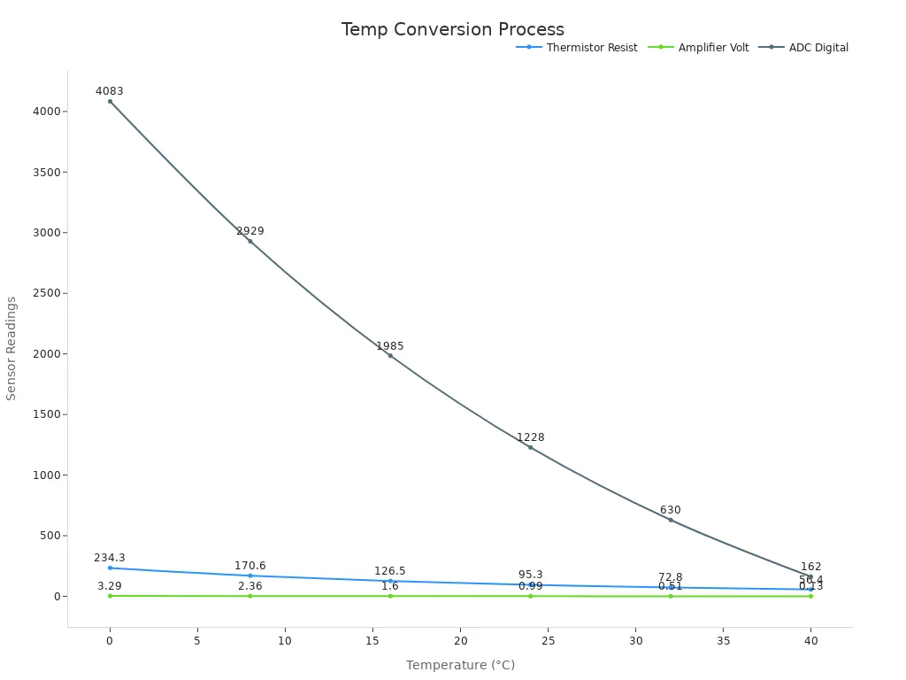
Tip: Using a Current-Loop Transmitter chip makes it easy to send accurate sensor data over long distances, even in noisy places.
Advantages and Limitations
Benefits in Industry
Current-loop transmitter chips give you several strong advantages when you need to send sensor data in tough environments. You can count on these systems for reliable performance, even when conditions are not ideal.
Noise Immunity: You do not have to worry about electrical noise. The current signal stays steady, so your data remains accurate, even near heavy machinery or long cables.
Long-Distance Reliability: You can run wires over long distances—sometimes hundreds of meters—without losing signal quality. The current does not drop, even if the voltage does.
Simple Wiring: You only need two wires for both power and signal. This makes installation easier and reduces costs.
Efficiency and Robustness: Newer chips use buck regulators, like the LT8618, which work better than older linear regulators. These buck regulators handle higher input voltages, give you more output current, and waste less energy as heat. They also fit into small spaces and stand up to harsh industrial conditions.
Easy Fault Detection: If a wire breaks or a device fails, the current drops below 4 mA. You can spot problems quickly and fix them before they cause bigger issues.
Tip: Buck regulators also help your system run cooler and more efficiently, especially when you need to step down high voltages.
Common Drawbacks
You should also know about the limits of current-loop transmitter chips. These systems are not perfect for every job.
Single-Signal Limitation: Each loop can only carry one signal. If you want to measure several things, you need more loops and more wiring.
Installation Constraints: You must match your power supply and load resistance carefully. If the load is too high, the chip cannot keep the current at the right level.
Hardware and Power Limits: Some chips, especially those with linear regulators, cannot provide much current. This limits how many features you can add to your system. Buck regulators improve this, but you still need to plan for power needs.
Complexity in Advanced Systems: When you use machine learning or advanced processing, you may run into power and hardware limits. Chips can only handle so many input channels or complex tasks before they run out of space or energy.
Reliability Concerns: Some devices have faced recalls due to malfunctions. You must choose reliable parts and test your system well.
Note: You may need extra protection, like TVS diodes, to guard against voltage surges in long loops. Always check your design for these risks.
You now see how a Current-Loop Transmitter chip helps you send sensor data with accuracy and reliability. This chip makes your measurements strong against noise and works well over long distances. The 4-20 mA standard gives you a simple way to spot problems fast. If you want a system that keeps your signals clear, consider using current loops in your next project.
FAQ
What happens if the current in the loop drops below 4 mA?
If the current drops below 4 mA, you know there is a problem. This could mean a broken wire, a failed sensor, or a power issue. You can quickly spot and fix the fault.
Can you use a current-loop transmitter chip with digital sensors?
Yes, you can use a current-loop transmitter chip with digital sensors. You need to convert the digital signal to an analog value first. The chip then changes this value into a 4-20 mA current.
How far can you run a 4-20 mA current loop?
You can run a 4-20 mA current loop for hundreds of meters. The signal stays strong over long distances. You must make sure your power supply can handle the total resistance in the loop.
Do you need special wiring for a current loop?
You do not need special wiring. Standard copper wires work well. Thicker wires help reduce voltage drop, especially for long runs. Always check the wire size for your distance and current needs.
Tip: Using the right wire size helps keep your signal accurate and your system reliable.
See Also
Understanding Current Controller Chips And Their Operation
A Clear Guide To Communication Chips And Their Functions
Simple Explanation Of Low-Dropout Linear Regulator Chips
