How to Configure and Program a 555 Timer IC

The 555 Timer IC is a small but powerful chip used in countless electronic circuits. Its ability to perform timing, oscillation, and pulse generation makes it a favorite among hobbyists and professionals. You can find it in applications such as LED flashers, motor controllers, and even educational tools.
Here are some of its versatile uses:
Delay timers and pulse-width modulation (PWM).
Frequency and tone generation.
LED flashers and light chasers.
Flip-flops and switch debouncing.
Motor and temperature control systems.
This Timer Programming Oscillator IC Chip remains a cornerstone of modern electronics, thanks to its reliability and ease of use.
Key Takeaways
The 555 Timer IC is useful for many projects like blinking LEDs, timing events, and controlling motors.
Knowing the pin setup is important to use it correctly. Each pin does a specific job that affects how the timer works.
The 555 Timer works in three ways: astable makes nonstop pulses, monostable makes one pulse, and bistable switches on and off. Pick the mode that fits your project.
Pin Configuration and Technical Specifications

Pin Layout of the 555 Timer IC
The 555 Timer IC has an 8-pin dual in-line package (DIP) layout. Each pin serves a specific purpose, making it easy to configure for various applications. Below is a table summarizing the pin layout:
Pin Number | Pin Name | Description |
|---|---|---|
1 | GND | Ground connection. |
2 | TRIG | Trigger input. Activates the timer when voltage drops below 1/3 of VCC. |
3 | OUT | Output pin. Provides the timer's output signal. |
4 | RESET | Resets the timer when a low signal is applied. |
5 | CONT | Control voltage. Adjusts the threshold and trigger levels. |
6 | THRES | Threshold input. Ends the timing interval when voltage exceeds 2/3 of VCC. |
7 | DISCH | Discharge pin. Discharges the timing capacitor. |
8 | VCC | Power supply. |
Functions of Each Pin
Each pin on the 555 Timer IC plays a critical role in its operation. For example:
Pin 2 (TRIG): Starts the timing cycle when the input voltage falls below a set threshold.
Pin 3 (OUT): Outputs either a high or low signal, depending on the timer's mode.
Pin 7 (DISCH): Controls the discharge of the external capacitor, influencing the timing interval.
These functions allow you to configure the IC for monostable, astable, or bistable modes.
Key Technical Specifications
The 555 Timer IC is designed to meet a wide range of technical requirements. Here are some key specifications:
Supply Voltage Range: Operates between +5V and +18V.
Timing Range: Adjustable from microseconds to several minutes.
Frequency Adjustment: Supports frequencies up to hundreds of kHz.
Load Current Capability: Handles up to 200mA, suitable for driving LEDs or small motors.
This versatility makes the 555 Timer IC a reliable choice for both simple and complex circuits.
Modes of Operation for the Timer Programming Oscillator IC Chip
The 555 Timer Programming Oscillator IC Chip operates in three primary modes: astable, monostable, and bistable. Each mode offers unique functionality, making the chip versatile for various applications.
Astable Mode: Continuous Oscillation
In astable mode, the Timer Programming Oscillator IC Chip generates a continuous stream of pulses. This mode has no stable state, meaning the output alternates between high and low states indefinitely. You can use this configuration for applications like LED flashers, clock signals, or tone generation.
Here’s how it works:
The chip charges and discharges a capacitor through two resistors (R1 and R2).
The output switches between high and low states based on the capacitor's voltage.
The high time interval for each pulse is calculated using the formula:t_high = ln(2)⋅(R1 + R2)⋅C
For example:
If R1 = 1kΩ, R2 = 2kΩ, and C = 10µF, the high time interval is approximately 30 milliseconds.
Key characteristics of astable mode include:
Continuous oscillation without external triggers.
Adjustable frequency and duty cycle by varying R1, R2, and C.
Tip: Use this mode when you need a consistent, repeating signal.
Monostable Mode: Single Pulse Generation
Monostable mode allows the Timer Programming Oscillator IC Chip to produce a single pulse when triggered. This mode has one stable state, and the output returns to this state after the pulse duration ends. It’s ideal for applications like timers, delay circuits, or pulse-width modulation.
When you apply an external trigger, the chip generates a pulse with a duration determined by the resistor (R1) and capacitor (C1). The pulse width is calculated using the formula:Output Pulse Width (secs) = 1.1 x R1 x C1
For instance:
If R1 = 100kΩ and C1 = 10µF, the pulse duration is 1.1 seconds.
Key characteristics of monostable mode include:
A single pulse output per trigger.
Precise control over pulse duration by adjusting R1 and C1.
Note: This mode is perfect for creating time delays or generating a single output signal in response to an event.
Bistable Mode: Flip-Flop Functionality
In bistable mode, the Timer Programming Oscillator IC Chip functions as a flip-flop. It has two stable states, and the output toggles between them when triggered. This mode is commonly used for toggle switches, memory storage, or latching circuits.
Here’s how it operates:
An external trigger switches the output from one state to the other.
The output remains in its current state until another trigger is applied.
Key characteristics of bistable mode include:
Two stable states for the output.
Requires external triggers to change states.
Mode | Characteristics | Stability | Trigger Requirement |
|---|---|---|---|
Astable | No stable states; oscillates between two states | None | None |
Monostable | One stable state; transitions to a temporary state with an external trigger | One state | External trigger |
Bistable | Two stable states; can switch between them with a trigger | Two states | External trigger |
Tip: Use bistable mode when you need a circuit to remember its state, such as in toggle switches or simple memory elements.
Each mode of the Timer Programming Oscillator IC Chip offers distinct advantages. By understanding these modes, you can configure the chip to meet your specific project requirements.
Step-by-Step Guide to Configuring the 555 Timer IC
Setting Up the IC in Astable Mode
To configure the 555 Timer IC in astable mode, you need to create a circuit that generates continuous pulses. This mode is ideal for applications like LED flashers or clock signals. Follow these steps to set up the circuit:
Connect the Power Supply: Attach pin 8 (VCC) to the positive terminal of your power source and pin 1 (GND) to the negative terminal.
Set Up the Timing Components:
Connect a resistor (R1) between pin 8 (VCC) and pin 7 (DISCH).
Place another resistor (R2) between pin 7 (DISCH) and pin 6 (THRES).
Attach a capacitor (C) between pin 6 (THRES) and pin 1 (GND).
Link the Trigger and Threshold Pins: Connect pin 6 (THRES) to pin 2 (TRIG) to allow the capacitor's voltage to control both the threshold and trigger levels.
Output Connection: Attach your output device (e.g., an LED) to pin 3 (OUT) through a current-limiting resistor.
Optional Adjustment: Use pin 5 (CONT) to fine-tune the timing by connecting it to a voltage divider or leaving it open for default operation.
The frequency and duty cycle of the output signal depend on the values of R1, R2, and C. For example, if R1 = 1kΩ, R2 = 2kΩ, and C = 10µF, the circuit will produce a square wave with a frequency of approximately 23 Hz. Experiment with different resistor and capacitor values to achieve your desired output.
Tip: Use this mode when you need a consistent, repeating signal for your project.
Configuring the IC in Monostable Mode
Monostable mode allows the 555 Timer IC to generate a single pulse when triggered. This configuration is perfect for creating timers or delay circuits. Here’s how you can set it up:
Power Connections: Connect pin 8 (VCC) to the positive terminal of your power supply and pin 1 (GND) to the negative terminal.
Timing Components:
Attach a resistor (R1) between pin 7 (DISCH) and pin 8 (VCC).
Connect a capacitor (C1) between pin 6 (THRES) and pin 1 (GND).
Trigger Input: Connect a push button or other triggering device to pin 2 (TRIG). Ensure the trigger voltage drops below 1/3 of VCC to activate the timer.
Output Connection: Attach your output device (e.g., an LED or buzzer) to pin 3 (OUT) through a current-limiting resistor.
Optional Adjustment: Use pin 5 (CONT) to modify the threshold voltage if needed.
When you press the trigger button, the circuit generates a single pulse with a duration determined by the formula:t = 1.1 × R1 × C1
For example, using the following components:
Component | Specification |
|---|---|
Timer IC | NE555 |
Resistors | 10kΩ |
Capacitors | 0.1μF |
Power Supply | 12V |
The pulse duration will be approximately 1.1 milliseconds. Adjusting the resistor or capacitor values changes the pulse length, offering flexibility for different applications.
In a practical setup, pressing the trigger button lights up an LED for the calculated duration. This demonstrates how the monostable mode works. You can use this configuration to create a delay timer or a one-shot pulse generator.
Note: Ensure the trigger signal is clean and free of noise to avoid false triggering.
Using the IC in Bistable Mode
Bistable mode transforms the 555 Timer IC into a flip-flop, allowing it to toggle between two stable states. This mode is useful for creating toggle switches or simple memory circuits. Follow these steps to configure the IC in bistable mode:
Power Connections: Connect pin 8 (VCC) to the positive terminal of your power source and pin 1 (GND) to the negative terminal.
Trigger Inputs:
Attach a push button to pin 2 (TRIG) to serve as the "set" input.
Connect another push button to pin 4 (RESET) to act as the "reset" input.
Output Connection: Attach your output device (e.g., an LED) to pin 3 (OUT) through a current-limiting resistor.
Optional Adjustment: Leave pin 5 (CONT) open or connect it to a voltage divider for additional control.
When you press the "set" button, the output switches to a high state and remains there until you press the "reset" button. This configuration is ideal for applications where you need the circuit to remember its state, such as in toggle switches or basic memory elements.
Tip: Use bistable mode when you need a circuit that maintains its state until explicitly changed.
Example Circuits and Applications

LED Flasher Circuit (Astable Mode)
The LED flasher circuit is a simple yet effective application of the 555 timer in astable mode. This configuration generates a continuous square wave, causing the LED to blink at regular intervals. The frequency of the blinking depends on the resistor and capacitor values in the circuit.
To build this circuit, you will need the following components:
A 555 timer IC
A 9V battery
A light-emitting diode (LED)
Two 47KΩ resistors
A 470KΩ resistor
A 1µF capacitor
Jumper wires
Tip: Adjusting the resistor and capacitor values changes the LED's flash frequency. Higher capacitance slows the blinking by extending the on and off phases.
The frequency of the square wave output is calculated as the reciprocal of the total period, which is the sum of the high and low times. For example:
Calculate the total period by adding the high and low times.
Find the frequency by taking the reciprocal of the period.
Replace the R2 resistor with a variable resistor to directly control the frequency and duty cycle.
This circuit demonstrates how you can use the 555 timer to create a visually engaging and functional project.
Timer Circuit for a Buzzer (Monostable Mode)
The timer circuit for a buzzer uses the 555 timer in monostable mode to produce a single pulse that activates the buzzer for a specific duration. This duration depends on the resistor and capacitor values, calculated using the formula:t = 1.1 × R × C
For example, using a 100KΩ resistor and a 10µF capacitor results in a pulse duration of approximately 1.1 seconds. You can adjust the timing by changing these components.
Desired Time | Resistor (R) | Capacitor (C) |
|---|---|---|
~1 second | 100KΩ | 10µF |
~5 seconds | 470KΩ | 10µF |
~10 seconds | 1MΩ | 10µF |
~30 seconds | 1MΩ | 47µF |
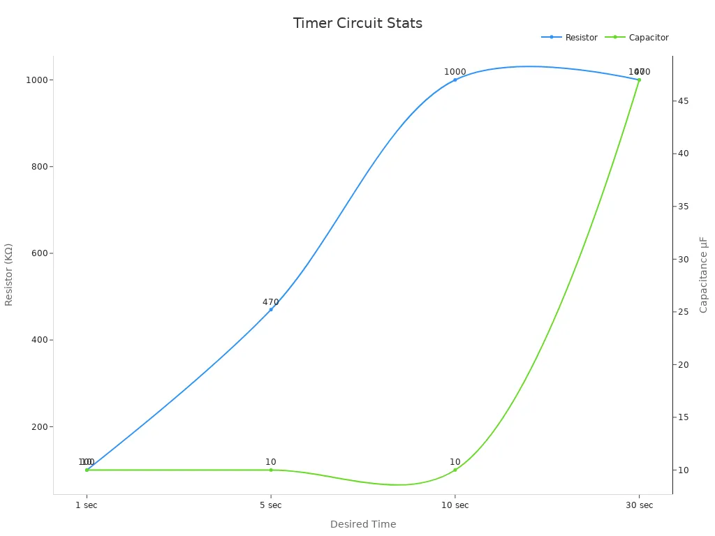
This circuit is ideal for applications requiring precise timing, such as alarms or delay circuits. The buzzer will sound for the calculated duration when triggered, making it a practical and educational project.
Toggle Switch Circuit (Bistable Mode)
The toggle switch circuit uses the 555 timer in bistable mode to function as a flip-flop. This configuration allows the output to toggle between high and low states based on external triggers. It is perfect for applications requiring stable outputs, such as logic circuits or memory cells.
When you press the "set" button, the output switches to a high state and remains there until you press the "reset" button. This stability ensures reliable performance in circuits that need to maintain their state until the next trigger.
This design highlights the versatility of the 555 timer in bistable mode. You can use it to create toggle switches, simple memory elements, or even basic control systems for larger projects.
Note: The 555 timer's ability to maintain stable outputs makes it a valuable component for circuits requiring consistent performance.
Troubleshooting Common Issues
Diagnosing Incorrect Output Signals
Incorrect output signals often result from improper component connections or incorrect values. Start by verifying the wiring of your circuit. Ensure each pin of the 555 timer IC connects to the correct components as per your design. Miswiring can cause the output to remain stuck in one state or oscillate unpredictably.
Next, check the resistor and capacitor values. Using incorrect values can alter the timing or frequency of the output signal. For example, if the capacitor's value is too low, the circuit may produce pulses that are too short to detect. Use a multimeter to confirm the actual values of your components.
Finally, inspect the trigger and threshold pins. Noise or interference on these pins can cause erratic behavior. Adding a small capacitor (e.g., 0.01 µF) between the control pin (pin 5) and ground can help stabilize the circuit.
Tip: Always double-check your circuit against the schematic before powering it on.
Resolving Power Supply Problems
A stable power supply is essential for the 555 timer IC to function correctly. Voltage fluctuations or noise on the VCC rail can disrupt the circuit's timing. For example, the ICM7555 datasheet highlights that frequency stability is affected by 0.5% per Volt of supply variation. This means even small voltage changes can significantly impact performance.
To troubleshoot power supply issues:
Use a decoupling capacitor (e.g., 10 µF) near the IC to filter out noise.
Check for voltage stability with a multimeter.
Ensure your power source provides sufficient current for the circuit.
Unstable power can cause frequency shifts. For instance, a timer circuit may oscillate at 2.7 kHz with a 5 V supply but increase to 3.3 kHz at 9 V. Addressing these issues ensures consistent and accurate operation.
Avoiding Common Circuit Design Mistakes
Design mistakes can lead to unreliable performance or even damage to components. One common error is neglecting to include a current-limiting resistor for LEDs connected to the output pin. Without this resistor, the LED may draw excessive current, potentially damaging the IC.
Another frequent mistake is using a capacitor with an incorrect voltage rating. Always choose a capacitor rated higher than the circuit's supply voltage to prevent failure. Additionally, avoid leaving unused pins floating. For example, connect the reset pin (pin 4) to VCC if it’s not used, ensuring the IC operates as intended.
Note: Careful planning and double-checking your design can save time and prevent frustration during troubleshooting.
The 555 Timer IC remains a cornerstone of electronics due to its versatility and reliability. You can use it in various applications, from simple LED flashers to advanced 3D electronics.
Application | Description |
|---|---|
Generates blinking LEDs in practical circuits. | |
Multilayer Embedded 3D Electronics | Powers modern designs with electrical schematics. |
Experiment with its configurations to unlock endless possibilities!
FAQ
How do I calculate the frequency in astable mode?
Use the formula:Frequency = 1 / (ln(2) × (R1 + 2 × R2) × C)
Replace R1, R2, and C with your component values.
Can I use the 555 Timer IC with a 3V power supply?
No, the 555 Timer IC requires a minimum of 5V to operate. Use a power source within the range of 5V to 18V.
What happens if I leave the RESET pin floating?
Leaving the RESET pin floating may cause erratic behavior. Connect it to VCC to ensure stable operation unless you need to use it actively.
See Also
Exploring The Basics Of Digital Integrated Circuit Technology
A Comprehensive Guide To Battery Charger Controller ICs
Applications Of Single Darlington Transistor Integrated Circuit Chips
Optocoupler IC Chips: Functionality And Applications Explained
