What is a Circuit Card Assembly and Why Does It Matter in Electronics
A circuit card assembly is a board that holds and connects electronic parts to make devices work. Circuit card assemblies play a crucial role in electronics because they act as the main control center for gadgets like phones and computers. Industry research shows that careful assembly and strong design choices, such as using thicker boards or better fastening methods, help devices last longer and work more reliably in daily life.
Key Takeaways
Circuit card assemblies are the heart of electronic devices, connecting parts to make gadgets like phones and cars work.
They combine a printed circuit board with electronic parts and connectors, creating a fully functional and tested unit.
Advanced assembly methods and quality checks ensure devices perform well and last longer, even in tough conditions.
These assemblies enable smaller, lighter, and more powerful devices by fitting many parts into compact spaces.
Circuit card assemblies support modern technology like smartphones, medical devices, and aerospace systems, making everyday life smarter and safer.
Circuit Card Assemblies Explained
What They Are
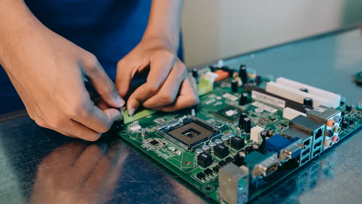
Circuit card assemblies form the core of most electronic devices. They start with a flat board called a printed circuit board (PCB). Engineers mount electronic parts like resistors, capacitors, and chips onto this board. The board has thin lines of metal, called traces, that connect these parts. These connections allow electricity to flow and signals to move between components. Circuit card assemblies act as the "brain" of a device, making sure all parts work together.
Circuit card assemblies perform several important roles in electronic devices:
They provide strong support for electronic parts.
They create paths for electrical signals.
They connect parts so they can share information.
They distribute power to each part.
They help the device connect to other systems.
They allow for complex designs by stacking layers.
These features help devices work reliably and efficiently.
Key Features
Circuit card assemblies stand out because of their careful design and assembly. They use both surface-mount and through-hole technologies. Surface-mount technology places tiny parts directly onto the board, while through-hole technology uses small holes for stronger connections. Many assemblies use both methods to balance size and strength.
Some key features include:
Precise placement of parts, often using machines that work with great accuracy.
Careful control of heat, using special materials and heatsinks to prevent overheating.
Special attention to signal quality, using controlled materials and careful layout to keep signals clear.
Support for very small parts, which helps make devices smaller and lighter.
Full testing before use, making sure each assembly works as expected.
Circuit card assemblies are more than just boards with parts. They are fully built and tested, ready to go into products that need high reliability, such as cars and airplanes.
Common Uses
Many industries rely on circuit card assemblies for their products. Some of the most common uses include:
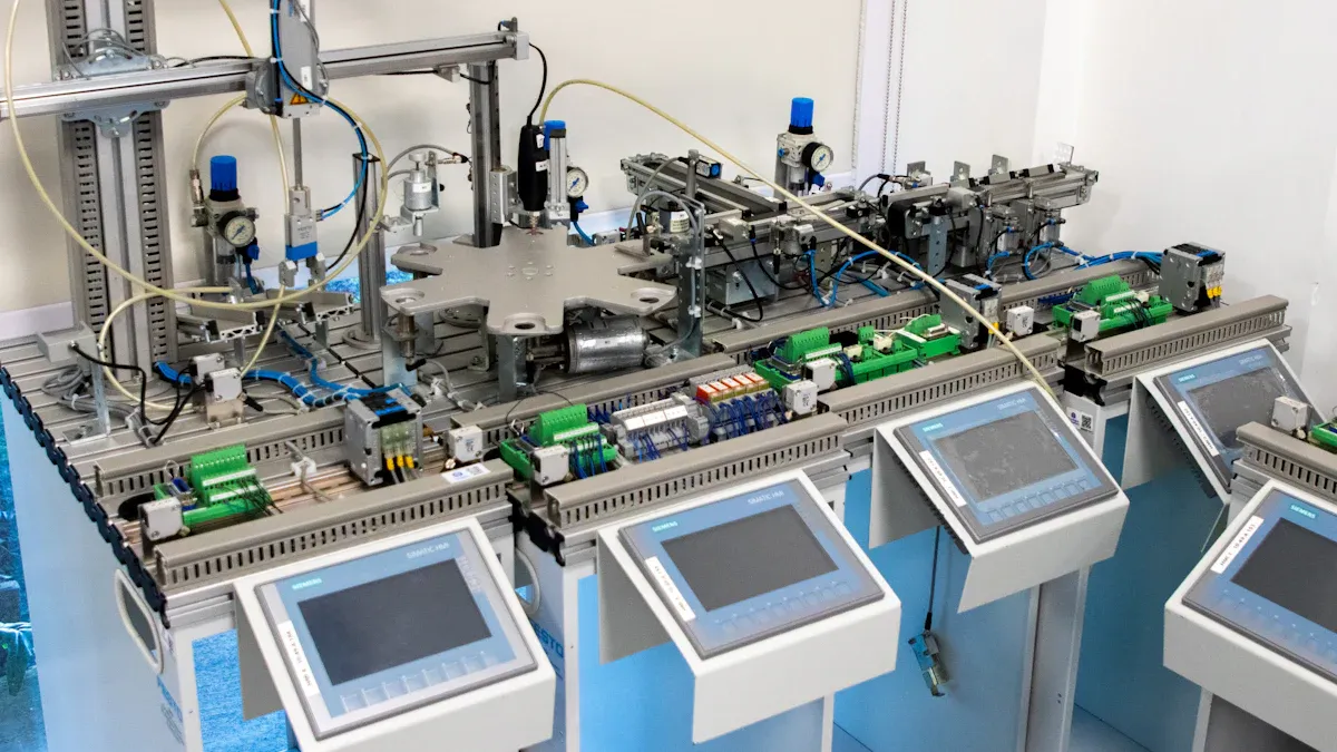
Industrial Automation: Used in robots and machines that build other products.
Automotive: Found in engine control units and car electronics.
Aerospace and Defense: Used in aircraft and military equipment.
Consumer Electronics: Found in laptops, gaming consoles, and smartphones.
Medical Devices: Used in machines like MRI scanners and patient monitors.
Telecommunications: Found in equipment that supports phone and internet networks.
The global market for these assemblies keeps growing. In 2023, the market reached $9.1 billion. Experts expect it to grow to $21.46 billion by 2032. This growth comes from rising demand in cars, airplanes, and everyday electronics.
Components and Structure
PCB Base
The printed circuit board (PCB) forms the foundation of every circuit card assembly. This base uses a non-conductive material, such as fiberglass or epoxy resin, with thin copper traces etched onto its surface. These traces create pathways for electricity to travel between components. The most common PCB material is FR-4, which offers good strength and insulation at a reasonable cost. Other materials, like polyimide or ceramic, appear in special applications that need flexibility or high heat resistance.
Material | Description/Composition | Key Properties/Uses |
|---|---|---|
FR-4 | Fiberglass-reinforced epoxy resin | Strong, affordable, widely used in electronics |
Polyimide | Polymer material | Flexible, good for wearable and medical devices |
Ceramic | Ceramic materials | High heat resistance, used in power electronics |
Aluminum | Metal base substrate | Excellent for heat management in LEDs and power supplies |
The PCB base supports all other parts and keeps them organized. Its copper traces connect everything together, making the board the backbone of the assembly.
Electronic Parts
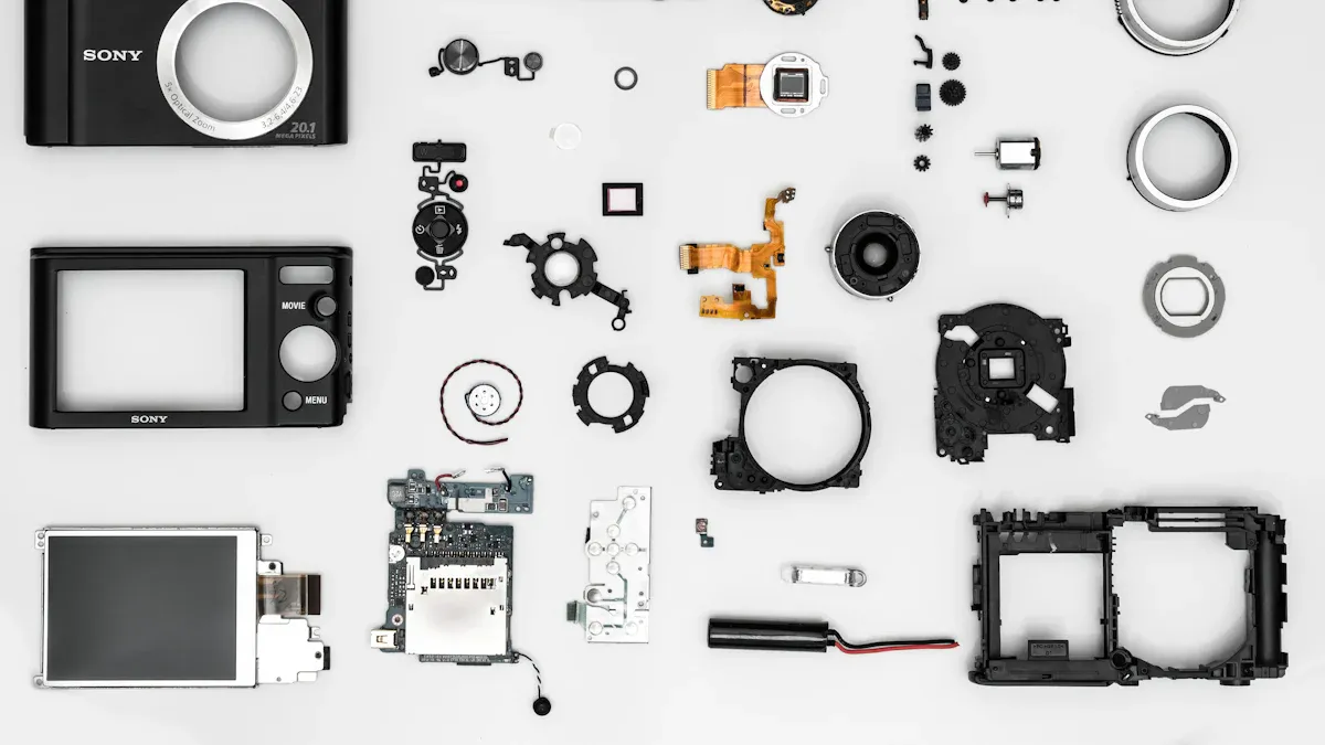
A circuit card assembly holds many types of electronic parts. These parts fall into two main groups: passive and active components.
Passive components:
Resistors limit current flow.
Capacitors store and release electric charge.
Inductors store energy in magnetic fields.
Crystals and oscillators provide timing signals.
Active components:
Diodes allow current to flow in one direction.
Transistors switch or amplify signals.
Integrated circuits (ICs) combine many functions in one chip.
LEDs emit light as indicators.
Other parts:
Potentiometers adjust voltage.
Relays and switches control circuit operation.
Manufacturers use surface-mount or through-hole methods to attach these parts. Each part receives a reference designator, such as "R" for resistor or "C" for capacitor, to help identify it on the board.
Connectors
Connectors play a key role in circuit card assemblies. These electromechanical devices link the PCB to other boards, wires, or external systems. They allow signals and power to move in and out of the assembly. Common connector types include wire-to-board, board-to-board, and wire-to-wire connectors. Each type ensures a secure fit and reliable electrical contact.
Connectors also make it easier to assemble, repair, or upgrade devices. Their design keeps signals clear and prevents loose connections. By joining all the parts together, connectors help the circuit card assembly work as a complete unit.
When all these elements—PCB base, electronic parts, and connectors—come together, they form a functional circuit card assembly. The copper traces carry signals and power between components, while connectors link the assembly to the rest of the device. This teamwork allows electronic devices to perform complex tasks quickly and reliably.
CCA vs. PCB vs. PCBA
PCB Overview
A printed circuit board (PCB) is the starting point for most electronics. This board is flat and made from materials like fiberglass. It has thin copper lines that create pathways for electricity. A PCB does not have any electronic parts attached to it. On its own, a PCB cannot do anything because it only provides the structure and the paths for signals. Manufacturers use special machines to make PCBs by layering materials, etching copper, and adding markings.
PCBA Overview
A printed circuit board assembly (PCBA) is a PCB with all the electronic parts attached. These parts include resistors, capacitors, chips, and connectors. Workers or machines place each part on the board using surface-mount or through-hole methods. After placing the parts, they solder them to make strong electrical connections. The PCBA goes through tests to make sure it works as expected. When finished, a PCBA can control devices, process signals, or power systems.
In many industries, people use the term circuit card assemblies to mean the same thing as PCBA. Both refer to a fully built board with all the needed components.
Key Differences
The main differences between PCB, PCBA, and circuit card assemblies can be seen in their function and how they are made. The table below shows a clear comparison:
Term | State/Definition | Functionality | Components Included | Manufacturing Step |
|---|---|---|---|---|
Printed Circuit Board (PCB) | Blank board with copper pathways, no parts | Not functional | None | First: board fabrication |
Printed Circuit Board Assembly (PCBA) | PCB with all parts mounted and soldered | All required components | Second: assembly and testing | |
Circuit Card Assembly (CCA) | Same as PCBA, fully assembled and tested board | Fully functional | All required components | Same as PCBA |
PCB is just the base.
PCBA and circuit card assemblies are the finished products that go into devices.
PCBA and CCA both use advanced assembly methods and testing to ensure quality.
Manufacturers first create the PCB, then add and solder parts to make a PCBA or circuit card assembly. Only after these steps does the board become ready to power electronic devices.
Assembly Process
Main Steps
Building a circuit card assembly involves several important steps. Each step helps ensure the final product works as designed. The process usually follows this order:
Technicians prepare the PCB by checking design files and making sure all parts match the plan.
Machines apply solder paste to the board using a stencil.
Inspectors check the solder paste to confirm it covers the right spots.
Automated machines place surface mount devices (SMDs) onto the board.
The board goes through a reflow oven, which melts the solder paste and secures the parts.
Cameras and computers perform an automatic optical inspection to spot any misplaced or missing parts.
Workers insert through-hole components into the board.
The board passes through a wave soldering machine to attach these larger parts.
Workers trim extra leads and perform a visual check.
Technicians run electrical tests to make sure the board works.
Some assemblies receive extra steps, such as coating for protection or programming chips.
Careful attention at each step helps prevent errors and improves reliability.
Mounting Technologies
Manufacturers use different methods to attach components to the PCB. The most common are Surface Mount Technology (SMT) and Through-Hole Technology (THT). Some assemblies use both methods to balance strength and size. The table below shows key features of popular mounting methods:
Mounting Method | Key Features | Advantages | Disadvantages |
|---|---|---|---|
Through-Hole Mounting | Leads go through board holes | Strong support, good for big parts | Slower, takes more space |
Surface Mount (SMT) | Parts sit on board surface | Fast, compact, fits small devices | Less strong, harder to inspect |
Mixed Technology | Uses both SMT and THT | Best of both worlds | More complex process |
Snap-Fit/Clip Mounting | Clips or slots hold parts | Quick, no tools needed | Not as strong |
Adhesive/Tape Mounting | Glue or tape holds parts | Cheap, saves space | Weak support, poor heat resistance |
SMT allows for smaller, lighter devices and faster assembly. THT gives extra strength and works well for heavy or high-power parts.
Quality Checks
Quality control plays a key role in circuit card assembly. Inspectors use several methods to catch problems early:
Solder paste inspection checks that paste covers the right areas.
Automated optical inspection uses cameras to find missing or misaligned parts.
X-ray inspection looks inside the board to check hidden connections.
In-circuit testing measures electrical values at different points.
Functional testing powers up the board to see if it works as expected.
Workers also perform visual checks under bright lights or with microscopes.
These checks help catch defects before the product leaves the factory. Careful testing and inspection lower failure rates and keep devices working longer.
Importance of Circuit Card Assemblies
Device Performance
Circuit card assemblies play a central role in how well electronic devices work. They allow engineers to fit more features into smaller spaces, which leads to lighter and more portable products. For example, smartphones and wearables use advanced assembly techniques to pack powerful processors, memory, and sensors onto tiny boards. This miniaturization makes devices easier to carry and use every day.
Smaller boards use less power, which helps batteries last longer and makes devices more eco-friendly.
High-density layouts let designers add more functions, such as cameras, wireless charging, and touchscreens, without making devices bigger.
Careful placement of parts and strong electrical connections keep signals clear and fast, which is important for high-speed devices like computers and tablets.
Good heat management, such as using special materials and thermal vias, keeps devices cool and prevents damage.
When engineers use precise machines to place and solder parts, they reduce errors and improve how well devices perform. Testing each board before it goes into a product ensures that everything works as planned.
Reliability
Reliability means that a device works well over time, even in tough conditions. Circuit card assemblies help achieve this by using strict quality controls and advanced inspection methods.
Automated machines place parts with great accuracy, which lowers the risk of mistakes.
Soldering processes use controlled heat to make strong joints, preventing loose connections that could cause failures.
Inspections, such as automated optical inspection (AOI) and in-circuit testing (ICT), catch problems early so faulty boards do not reach customers.
Good thermal management, like adding heatsinks or special pathways for heat, reduces the chance of overheating.
Careful documentation and regular process reviews help keep quality high and defects low.
Medical devices, such as ventilators and patient monitors, depend on these high standards. In aerospace, circuit card assemblies power flight control systems, navigation modules, and communication radios. These applications require boards that can handle vibration, temperature changes, and long hours of use without failing.
Strict quality checks and reliable assembly methods make sure that devices in critical fields, like medicine and aviation, stay safe and dependable.
Enabling Modern Tech
Advances in circuit card assembly technology have made many modern devices possible. The rise of the Internet of Things (IoT) and wearable electronics depends on small, flexible, and powerful boards.
High-frequency boards support fast data transfer, which is needed for 5G phones and smart home devices.
Flexible and durable designs allow engineers to create wearables that fit on wrists, clothing, or even inside shoes.
Combining sensors, processors, and wireless modules on one board lets devices do more while staying small.
Careful power management helps extend battery life, which is important for portable gadgets.
Automated assembly and inspection make it possible to build millions of reliable devices quickly.
Aerospace systems use circuit card assemblies in flight computers, radar, and satellite links. Household electronics, such as smart thermostats and LED lights, also rely on these assemblies to work smoothly and connect with other devices.
Without these advances, many of today’s smart, connected, and portable devices would not exist.
Circuit card assemblies transform simple boards into the backbone of modern electronics. They use precise tools and advanced techniques to place and connect components, ensuring devices work reliably.
They enable compact, powerful designs for everything from smartphones to medical equipment.
Quality control and testing keep performance high and failures low.
Engineers and hobbyists who learn about these assemblies can create better, more reliable projects.
For those interested in learning more, many resources offer guides, design tips, and project ideas on circuit card assembly and electronics.
FAQ
What is the main purpose of a circuit card assembly?
A circuit card assembly connects and supports electronic parts. It lets electricity and signals move between components. This assembly helps devices work as designed.
How does a CCA differ from a PCB?
A PCB is just the board with copper paths. A CCA has the board plus all the electronic parts attached. Only the CCA can make a device function.
Where can people find circuit card assemblies in daily life?
People see circuit card assemblies in many places:
Smartphones
Laptops
Home appliances
These assemblies power most modern electronics.
Why do manufacturers test circuit card assemblies?
Manufacturers test circuit card assemblies to catch problems early. Testing ensures each board works correctly and safely. This process helps devices last longer and perform better.
See Also
A Comprehensive Guide To Digital Integrated Electronic Circuits
How Communication Chips Function And Their Key Features
The Role Of ESD Protection Chips In Electronics
Why MCUs With FPUs Are Important For Embedded Systems
Exploring The Importance Of Integrated Circuits In Electronics
