How to Design and Build an Audio Power Amplifier Circuit in 2025
An audio power amplifier circuit boosts weak audio signals to drive speakers, ensuring clear and powerful sound output. It plays a vital role in home audio systems, portable devices, and professional setups. In 2025, technological advancements have made building such circuits more exciting than ever.
The popularity of DIY projects has surged:
More consumers seek home audio upgrades.
Customization trends drive demand for flexible amplifier designs.
High-performance amplifiers tailored to specific needs are in demand.
Recent innovations enhance accessibility for enthusiasts. Class-D amplifiers achieve over 90% efficiency, reducing heat and enabling compact designs. Gallium Nitride transistors improve sound fidelity while minimizing distortion. AI-driven signal processing adds features like noise cancellation and energy efficiency. These advancements empower you to create amplifiers with superior performance and sustainability.
DIY amplifier projects also offer unique benefits. You gain control over design and features, plus valuable hands-on experience. By building your own amplifier, you can customize it to suit your preferences while developing technical skills.
Key Takeaways
Making your own audio amplifier is becoming popular. It lets you customize and improves your technical skills.
Class D amplifiers work very well, with over 90% efficiency. They are great for portable devices and stay cooler.
Knowing things like gain, bandwidth, and efficiency is important. These help make your amplifier sound better and work well.
Keeping the amplifier cool is very important. Use heat sinks, thermal pads, and good airflow to stop overheating.
Being eco-friendly in amplifier design is important too. Pick green parts and methods to help the planet while keeping good performance.
Understanding Audio Power Amplifier Circuits
Types of Amplifiers: Class A, B, AB, and D
Audio power amplifier circuits come in various classes, each with unique characteristics. Class A amplifiers provide excellent sound quality due to their high linearity. However, they are inefficient, with only about 20% efficiency, as they continuously draw current. Class B amplifiers improve efficiency to over 60% by using two transistors to handle positive and negative halves of the signal. Unfortunately, they can introduce crossover distortion, which affects sound quality. Class AB amplifiers combine the strengths of Class A and B, offering better sound quality and moderate efficiency (60-65%). Finally, Class D amplifiers stand out with over 90% efficiency. They use pulse-width modulation to minimize heat generation, making them ideal for portable and battery-powered devices.
Amplifier Class | Sound Quality Characteristics | |
|---|---|---|
Class A | ~20 | High linearity, but generates significant heat |
Class B | >60 | Better efficiency, but can introduce distortion |
Class AB | 60 - 65 | Combines benefits of A and B, reduced distortion |
Class D | >90 | Very high efficiency, low heat generation, but different operational principles |
Choosing the Right Amplifier for Your Application
Selecting the right amplifier depends on your specific needs. For high-fidelity audio systems, Class A amplifiers are a great choice due to their superior sound quality. If efficiency is more critical, such as in portable devices, Class D amplifiers are ideal. Class AB amplifiers work well for home audio systems, offering a balance between sound quality and efficiency. Class B amplifiers are less common due to their distortion issues but may suit applications where cost is a priority. Consider factors like power requirements, heat dissipation, and the intended use of your audio power amplifier circuit when making your decision.
Tip: For battery-operated devices, prioritize efficiency to extend battery life. Class D amplifiers are often the best option in such cases.
Key Performance Metrics: Gain, Bandwidth, and Efficiency
When designing an audio power amplifier circuit, understanding key performance metrics is essential. Gain measures how much the amplifier boosts the input signal. A higher gain indicates better amplification but can also introduce noise. Bandwidth defines the range of frequencies the amplifier can handle. Most amplifiers perform well within the 20Hz to 20kHz range, which covers the human hearing spectrum. Efficiency, especially power-added efficiency (PAE), determines how effectively the amplifier converts power into sound. Modern designs, like Class D amplifiers, achieve efficiencies above 90%, making them highly energy-efficient.
Gain: Amplifiers should limit gain below 20Hz to avoid unwanted frequencies.
Bandwidth: Frequencies above 20kHz do not significantly improve audio quality.
Efficiency: High efficiency is crucial for devices with limited power supply, such as portable speakers.
By balancing these metrics, you can optimize your amplifier for both performance and energy consumption.
Planning and Preparing for Your Project
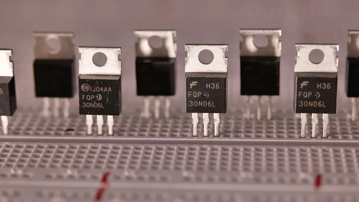
Essential Components: Transistors, Resistors, Capacitors, and More
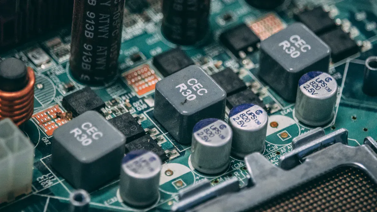
To build an audio power amplifier circuit, you need a set of essential components. Transistors act as the backbone, amplifying the input signal. You can choose between Bipolar Junction Transistors (BJTs) or Field Effect Transistors (FETs), depending on your design. Resistors control current flow and set the gain of your amplifier. Capacitors filter noise and stabilize the power supply, ensuring smooth operation. Inductors may also be necessary for Class D amplifiers to handle high-frequency signals effectively.
You will also need a reliable power supply unit (PSU) to provide the required voltage and current. Heat sinks are crucial for managing heat dissipation, especially in high-power designs. Don’t forget connectors, wires, and a printed circuit board (PCB) to assemble your circuit neatly. By gathering these components, you’ll have the foundation for a successful project.
Tools and Software for Circuit Design and Assembly
Having the right tools makes your project easier and more efficient. A soldering iron is essential for assembling your circuit. Use a multimeter to test connections and measure voltage, current, and resistance. Oscilloscopes help you visualize signal waveforms, which is vital for troubleshooting. Wire cutters, pliers, and a screwdriver set are also handy.
For design, modern software tools like KiCAD and LTspice simplify the process. KiCAD allows you to create schematics and PCB layouts, while LTspice helps simulate your circuit’s performance. In 2025, AI-assisted tools have become popular. These tools can optimize your design by suggesting improvements, saving you time and effort.
Sourcing Components in 2025: Online Platforms and Eco-Friendly Options
Finding components for your audio power amplifier circuit has never been easier. Online platforms like Digi-Key, Mouser, and Element14 offer a wide range of parts. Many of these platforms now highlight eco-friendly options, reflecting the growing demand for sustainable practices.
The market for eco-friendly components is expanding due to increased awareness of sustainability.
Manufacturers are adopting recyclable packaging and lead-free solder in their kits.
Government regulations in North America and Europe encourage the use of sustainable materials.
You can also find amplifier kits designed with energy-efficient components and low-power consumption circuits. These kits not only reduce environmental impact but also improve the overall efficiency of your design. By choosing eco-conscious options, you contribute to a greener future while building a high-performance amplifier.
Designing the Audio Power Amplifier Circuit
Power Supply Design and Voltage Requirements
The power supply is the backbone of your audio power amplifier circuit. It determines the voltage and current available to your amplifier, directly impacting its performance. A well-designed power supply ensures stable operation, minimizes noise, and prevents damage to components. You must choose a power supply that matches the voltage and current requirements of your amplifier design.
Linear power supplies are common in audio applications due to their low noise levels. However, they can be bulky and less efficient. Switching power supplies, on the other hand, are compact and efficient but may introduce noise if not properly filtered. Selecting the right type depends on your amplifier's class and intended use.
"The complexities of power supply design for audio amplifiers highlight the importance of proper voltage requirements. Different power supply types significantly affect amplifier performance."
When designing the power supply, consider the voltage rails required by your amplifier. For example, a Class AB amplifier might need dual voltage rails, such as ±15V, to operate effectively. Ensure the power supply can handle peak current demands during high-volume playback. Adding capacitors to the power supply helps smooth voltage fluctuations and reduces ripple, improving sound quality.
Calculating Key Parameters: Gain, Impedance, and Bandwidth
Accurate calculations of gain, impedance, and bandwidth are essential for optimizing your audio power amplifier circuit. These parameters define how the amplifier processes and outputs audio signals.
Gain: Gain measures how much the amplifier boosts the input signal. For example, a low-frequency gain of 14 dB ensures adequate amplification without introducing noise.
Impedance: Matching the input and output impedance of your amplifier with the connected devices minimizes signal loss and distortion.
Bandwidth: The bandwidth determines the range of frequencies the amplifier can handle. A typical amplifier should cover the 20Hz to 20kHz range for full-spectrum audio.
Parameter | Value |
|---|---|
Low Frequency Gain | 14 dB |
3 dB Down Point (f2) | 167 kHz |
Unity Gain Frequency | 2.05 MHz |
To calculate these parameters, use basic circuit analysis techniques. For instance, you can determine gain by dividing the output voltage by the input voltage. Impedance calculations involve analyzing the resistance and reactance in the circuit. Bandwidth can be measured by identifying the frequency range where the amplifier maintains consistent gain.
The transimpedance gain of an optical receiver front-end, for example, can be derived using Kirchhoff’s current law. This method applies to high-speed designs and ensures accurate determination of gain and bandwidth.
Using Modern Design Tools: KiCAD and AI-Assisted Software
Modern tools like KiCAD and AI-assisted software have revolutionized the design process for audio power amplifier circuits. These tools simplify complex tasks, reduce errors, and save time.
KiCAD is a free, open-source software that allows you to create schematics and PCB layouts. It offers a user-friendly interface and supports multi-layer PCB designs. You can use KiCAD to visualize your circuit, place components, and generate Gerber files for PCB fabrication.
AI-assisted tools take circuit design to the next level. They optimize your design by detecting flaws, predicting failures, and suggesting improvements. For example:
AI-driven tools can automatically identify potential design flaws, reducing human error.
Cloud-based solutions enable real-time collaboration, allowing you to work on your design from anywhere.
Advanced simulation features let you test your circuit virtually, speeding up prototyping and reducing costs.
These advancements make it easier than ever to design high-performance amplifiers. By leveraging these tools, you can create efficient, reliable circuits with minimal effort.
Managing Heat Dissipation and Thermal Stability
Heat management is a critical aspect of designing an audio power amplifier circuit. Excessive heat can degrade performance, reduce component lifespan, and even cause circuit failure. You must address heat dissipation and ensure thermal stability to maintain reliable operation.
Why Heat Dissipation Matters
When your amplifier operates, it generates heat due to power losses in components like transistors and resistors. If this heat accumulates, it can lead to thermal runaway—a condition where rising temperatures cause components to draw more current, generating even more heat. This cycle can damage your circuit. Proper heat management prevents this and ensures consistent performance.
Effective Methods for Managing Heat
You can use several techniques to manage heat in your amplifier circuit:
Heat Sinks: Attach heat sinks to power transistors or other heat-generating components. These metal structures increase the surface area for heat dissipation, allowing heat to escape more efficiently.
Thermal Pads and Compounds: Place thermal pads or apply thermal paste between components and heat sinks. These materials improve thermal conductivity by filling microscopic gaps.
Active Cooling: Use small fans to actively cool the circuit. Fans are especially useful for high-power amplifiers that generate significant heat.
Ventilation: Design your amplifier enclosure with proper ventilation. Airflow helps dissipate heat naturally.
Thermoelectric Coolers (TECs): TECs are advanced cooling devices that can lower temperatures below ambient levels. They are compact and effective for managing heat in high-performance circuits.
Note: Thermoelectric coolers have been successfully used in electronics like aircraft systems. Research shows that TECs can maintain temperatures well below operational limits, ensuring thermal stability even under demanding conditions.
Ensuring Thermal Stability
Thermal stability ensures your amplifier operates consistently across temperature changes. You can achieve this by:
Choosing Temperature-Resistant Components: Use components rated for high temperatures. For example, transistors with a wide operating temperature range perform better in heat-intensive environments.
Implementing Thermal Feedback: Some amplifier designs include thermal feedback mechanisms. These systems monitor temperature and adjust the circuit's operation to prevent overheating.
Simulating Thermal Performance: Use circuit simulation software to predict how your design handles heat. Tools like LTspice allow you to model thermal behavior and identify potential issues before assembly.
Practical Tips for Heat Management
Position heat-generating components away from sensitive parts like capacitors. Heat can degrade capacitor performance over time.
Avoid overcrowding components on your PCB. Spacing them out improves airflow and reduces heat buildup.
Test your amplifier under real-world conditions. Measure temperatures during operation to ensure your cooling methods are effective.
By implementing these strategies, you can build an amplifier that remains cool and stable, even during extended use. Proper heat management not only enhances performance but also extends the life of your audio power amplifier circuit.
PCB Design and Fabrication for Amplifiers
Creating a PCB Layout for Your Circuit
Designing a PCB layout is a critical step in building your audio power amplifier circuit. A well-planned layout ensures optimal performance and minimizes issues like noise and interference. Start by arranging components logically. Place power supply components near the input to reduce voltage drops. Keep signal paths short and direct to avoid signal loss.
To reduce crosstalk, maintain adequate spacing between traces. Avoid placing traces too close to each other, especially those carrying high-frequency signals. Minimize abrupt turns in traces, as these can increase crosstalk and signal distortion. Studies show that traces with fewer turning points and greater separation experience less interference. Group related components together to simplify routing and improve signal integrity.
Generating Gerber Files and Ordering PCBs
Gerber files are essential for manufacturing your PCB. These files contain detailed information about each layer of your design, including copper traces, solder masks, and silkscreen layers. Manufacturers rely on these files to produce your PCB accurately. Ensure your Gerber files adhere to industry standards, such as the RS-274X format, to avoid fabrication errors.
Before submitting your files, verify them using a Gerber viewer. This step helps you catch mistakes like missing layers or incorrect dimensions. Once verified, upload your files to a trusted PCB manufacturer. Many online platforms offer quick turnaround times and affordable pricing. Gerber files streamline the manufacturing process, ensuring precision and reducing production delays.
Ensuring Quality and Avoiding Common PCB Design Mistakes
Quality assurance is vital for a reliable PCB. Common mistakes, such as leaving unused op-amp inputs floating, can cause noise and unexpected behavior. Inadequate power supply design may lead to instability and voltage fluctuations. Ignoring parasitic inductance or capacitance can result in signal deterioration and resonance issues, especially in high-speed circuits.
Common Mistakes | Impact on Performance |
|---|---|
Leaving unused op-amp inputs floating | Can lead to unexpected behavior, increased current consumption, and noise pickup. |
Inadequate power supply design | Results in circuit instability, noise, and voltage fluctuations. |
Ignoring parasitic inductance/capacitance | Causes instability, signal deterioration, and unexpected resonances, especially in high-speed circuits. |
To ensure quality, use robust materials like 2oz copper for better conductivity. Apply thermal management techniques to handle heat effectively. Test your PCB under real-world conditions to validate its performance. For example, industrial automation systems have achieved high efficiency and passed safety certifications by using advanced materials and thorough testing. These practices ensure your amplifier operates reliably and meets performance expectations.
Building and Testing the Audio Power Amplifier Circuit
Step-by-Step Assembly and Soldering Techniques
Assembling your audio power amplifier circuit requires precision and patience. Start by organizing all components and tools on a clean, well-lit workspace. This preparation minimizes errors and ensures a smooth assembly process.
Prepare the PCB: Begin by inspecting the printed circuit board (PCB) for any manufacturing defects. Check for broken traces or irregularities that could affect performance. If everything looks good, secure the PCB on a stable surface to prevent movement during soldering.
Insert Components: Place the smallest components, such as resistors and diodes, onto the PCB first. Insert them into their designated slots, ensuring the correct orientation. For polarized components like capacitors, double-check the polarity markings.
Solder Connections: Heat your soldering iron to the recommended temperature (typically 350–400°C). Apply a small amount of solder to the tip to improve heat transfer. Touch the soldering iron to the component lead and the PCB pad simultaneously, then feed solder into the joint. Remove the iron once the solder flows smoothly. Avoid using too much solder, as this can create bridges between adjacent pads.
Trim Excess Leads: After soldering, use wire cutters to trim any excess component leads sticking out from the PCB. This step ensures a neat and professional finish.
Inspect and Test: Examine each solder joint for proper adhesion and shine. Dull or cracked joints may indicate a cold solder joint, which can cause connectivity issues. Reheat and re-solder any problematic joints. Use a multimeter to test continuity and verify that all connections are secure.
Tip: Practice soldering on a scrap PCB if you're new to the process. This will help you build confidence and improve your technique.
Wiring and Designing the Enclosure
Proper wiring and enclosure design protect your amplifier and enhance its performance. Follow these guidelines to ensure a professional and functional build:
Wiring Tips:
Use color-coded wires to differentiate between power, ground, and signal connections. This makes troubleshooting easier.
Keep signal wires as short as possible to reduce noise and interference.
Twist power and ground wires together to minimize electromagnetic interference (EMI).
Grounding Considerations:
Proper grounding is essential to avoid ground loops, which can introduce hum or noise into your audio output. Connect all ground points to a single star ground to maintain consistency.
Avoid connecting multiple ground paths, as this can create loops that degrade sound quality.
Enclosure Design:
Metal enclosures provide excellent shielding against electromagnetic fields, preserving sound integrity. Aluminum or steel cases are popular choices.
Ensure the enclosure has proper ventilation to dissipate heat. Drill holes or add vents near heat-generating components like transistors and heat sinks.
Position input and output connectors away from the power supply to reduce interference.
Install Components: Secure the PCB, power supply, and connectors inside the enclosure using screws or standoffs. Ensure all components are firmly attached to prevent movement.
Route Wires: Organize wires neatly using zip ties or cable clips. Keep power and signal wires separate to avoid crosstalk.
Test Fit: Before finalizing the assembly, test-fit the enclosure to ensure all components fit comfortably. Adjust placements if necessary.
Note: Using non-metallic enclosures can lead to poor grounding and increased susceptibility to external interference. Metal enclosures are highly recommended for optimal performance.
Safety Precautions During Assembly
Working with electronic components involves risks, especially when dealing with high voltages. Prioritize safety to protect yourself and your equipment.
General Safety Tips:
Always work in a well-ventilated area to avoid inhaling fumes from soldering.
Wear safety goggles to protect your eyes from solder splashes or flying debris.
Keep your workspace dry and free of clutter to prevent accidents.
Handling High Voltages:
Many amplifier circuits, especially tube-based designs, operate at lethal voltages. Never touch live circuits or components while the power is on.
Discharge capacitors before handling the circuit. Use a resistor to safely bleed off stored charge.
Use insulated tools and wear rubber-soled shoes to reduce the risk of electric shock.
Testing Precautions:
Double-check all connections before powering up the circuit. Incorrect wiring can damage components or cause short circuits.
Use a current-limited power supply during initial testing to prevent excessive current flow in case of a fault.
Monitor the circuit for unusual behavior, such as overheating or smoke. Turn off the power immediately if you notice any issues.
Warning: You are responsible for taking every precaution when working with high-voltage circuits. Mishandling these circuits can result in serious injury or damage.
By following these steps and precautions, you can safely assemble and test your audio power amplifier circuit. A careful approach ensures a reliable and high-performing amplifier that you can enjoy for years to come.
Testing and Troubleshooting for Optimal Performance
Testing and troubleshooting are essential steps to ensure your audio power amplifier circuit performs at its best. These processes help you identify potential issues, fine-tune the design, and achieve optimal sound quality. Follow these steps to test and troubleshoot your amplifier effectively.
Step 1: Initial Power-Up and Visual Inspection
Before applying full power, perform a low-voltage test. Use a current-limited power supply to prevent damage in case of wiring errors. Check for any unusual signs, such as overheating components, smoke, or strange smells. Inspect solder joints and connections for visible defects. Loose or cold solder joints can cause intermittent issues or complete circuit failure.
Tip: Use a magnifying glass to examine solder joints closely. A shiny, smooth joint indicates a good connection, while dull or cracked joints may need re-soldering.
Step 2: Measuring Key Performance Metrics
Use testing equipment to measure critical parameters of your amplifier. These measurements help you verify that the circuit meets design specifications.
Total Harmonic Distortion (THD): THD measures the distortion introduced by the amplifier. Aim for a THD level that matches your application. For example:
THD Level
Interpretation
≤ 1 % THD
Reference-quality hi-fi driver
2–5 % THD
Average consumer loudspeaker (audible but tolerated)
< 0.01 % THD+N
Quality Class-D/AB amplifier
≈ 0.0002 % THD+N
Best-in-class Class-D module
Gain and Bandwidth: Measure the amplifier's gain to ensure it amplifies the input signal correctly. Verify that the bandwidth covers the desired frequency range (e.g., 20Hz to 20kHz for audio applications).
Impedance Matching: Proper impedance matching is crucial. Mismatched impedance can lead to clipping, distortion, or reduced efficiency. Check the minimum impedance (Zmin) of your amplifier and ensure it aligns with the connected speakers.
Step 3: Signal Testing with an Oscilloscope
Connect an oscilloscope to the amplifier's output to visualize the signal waveform. Feed a sine wave signal into the amplifier and observe the output. A clean, undistorted waveform indicates proper operation. Look for signs of clipping, which occurs when the amplifier exceeds its power limits. Adjust the input signal or gain settings to eliminate clipping.
Note: Clipping not only distorts sound but can also damage speakers over time. Always test at various input levels to ensure the amplifier handles dynamic audio signals effectively.
Step 4: Troubleshooting Common Issues
If your amplifier doesn't perform as expected, use these troubleshooting tips to identify and resolve problems:
No Output Signal:
Verify all connections and ensure the power supply is functioning.
Check for blown fuses or damaged components.
Test the input signal to confirm it reaches the amplifier.
Distorted Sound:
Inspect the impedance matching between the amplifier and speakers.
Replace any faulty components, such as transistors or capacitors.
Ensure the power supply provides stable voltage without fluctuations.
Overheating:
Confirm that heat sinks are properly attached and thermal paste is applied.
Improve ventilation in the enclosure to enhance airflow.
Reduce the amplifier's load by lowering the output power.
Step 5: Fine-Tuning for Optimal Performance
Once the amplifier passes basic tests, fine-tune it for the best performance. Adjust the bias current in Class AB amplifiers to minimize crossover distortion. For Class D designs, optimize the switching frequency to balance efficiency and sound quality. Use advanced tools, such as AI-assisted software, to identify performance bottlenecks and suggest improvements.
Dr. Perri Needham emphasizes the importance of tools in identifying bottlenecks, while Dr. Markus Rampp highlights their role in optimizing workflows. Leverage these insights to refine your amplifier's design.
Final Testing and Benchmarking
After troubleshooting, conduct a final round of testing to benchmark your amplifier's performance. Compare the results against industry standards to ensure your design meets expectations. For example, a THD+N level below 0.01% indicates a high-quality amplifier suitable for professional audio systems.
By following these steps, you can test and troubleshoot your audio power amplifier circuit with confidence. A systematic approach ensures your amplifier delivers clear, distortion-free sound and operates reliably under various conditions.
Advanced Tips and Future Trends in Amplifier Design
Emerging Technologies: AI-Assisted Tuning and Smart Amplifiers
AI-assisted tuning and smart amplifiers are transforming how audio systems perform. These technologies adapt sound output based on real-time conditions, ensuring an immersive listening experience. For example, smart amplifiers can adjust audio settings depending on ambient noise levels or user preferences. This innovation is particularly useful in environments like vehicles, where sound quality can vary due to road noise or cabin acoustics.
Key trends driving these advancements include:
AI-driven audio systems that optimize sound based on cabin conditions.
Increased demand for advanced audio solutions in electric and connected vehicles.
Collaborations between automotive manufacturers and audio technology firms to enhance in-cabin experiences.
These developments highlight the growing importance of intelligent audio systems. By incorporating AI into your audio power amplifier circuit, you can create a design that delivers superior sound quality and adapts to dynamic environments.
Eco-Friendly Components and Sustainable Design Practices
Sustainability is becoming a priority in amplifier design. Eco-friendly components reduce environmental impact while maintaining high performance. Manufacturers now offer recyclable packaging, lead-free solder, and energy-efficient parts. These options align with global efforts to minimize electronic waste.
To make your amplifier project more sustainable:
Choose components with low power consumption.
Use recyclable materials for the enclosure.
Opt for suppliers that prioritize eco-friendly practices.
Sustainable design not only benefits the environment but also enhances the efficiency of your amplifier. By adopting these practices, you contribute to a greener future while building a reliable audio system.
Optimizing Sound Quality and Energy Efficiency
Balancing sound quality and energy efficiency is essential for modern amplifier designs. High-quality sound requires precise signal processing and minimal distortion. At the same time, energy-efficient designs reduce power consumption and heat generation.
To optimize sound quality:
Use low-distortion transistors and capacitors.
Implement noise-canceling circuits to eliminate interference.
Test your amplifier across different frequencies to ensure consistent performance.
For energy efficiency:
Select components with high power-added efficiency (PAE).
Incorporate Class D amplifier technology, which achieves over 90% efficiency.
Design circuits that minimize power loss during operation.
By focusing on these aspects, you can create an amplifier that delivers exceptional audio performance without compromising energy usage.
Designing and building an audio power amplifier circuit involves several essential steps. Start by developing detailed specifications and creating a block diagram to outline the circuit's architecture. Place bypass, coupling, and decoupling capacitors to stabilize the DC supply and improve audio quality. Integrate pull-up and pull-down resistors to maintain stable logic levels and prevent erratic behavior. These practices ensure a reliable and high-performing amplifier.
Experimentation is key to innovation. Try different components, explore new designs, and refine your amplifier for optimal sound quality. Resources like the Audio Power Amplifier Design Handbook by Douglas Self offer valuable insights into amplifier principles and stability.
For further learning, explore these resources:
By following these steps and exploring additional resources, you can create amplifiers that deliver exceptional sound and performance.
FAQ
What is the best amplifier class for beginners to build?
Class AB amplifiers are ideal for beginners. They balance sound quality and efficiency, making them easier to design and troubleshoot. You can also find many resources and tutorials to guide you through the process.
How do you calculate the gain of an amplifier?
Divide the output voltage by the input voltage to calculate gain. For example, if the input is 1V and the output is 10V, the gain is 10. Use a multimeter to measure these voltages accurately.
Can you use a breadboard to build an amplifier circuit?
Breadboards work for prototyping low-power circuits. However, they are unsuitable for high-power amplifiers due to poor connections and heat management. Use a PCB for better performance and reliability.
How do you prevent noise in your amplifier circuit?
Keep signal wires short and separate from power wires. Use shielded cables for audio signals. Add decoupling capacitors near power supply pins to filter noise effectively.
What tools are essential for testing an amplifier?
You need a multimeter, oscilloscope, and signal generator. A multimeter checks voltage and continuity. An oscilloscope visualizes waveforms, while a signal generator provides test signals for performance evaluation.
See Also
Emerging Trends Influencing the Analog IC Sector by 2025
Understanding IC Audio Signal Processors And Their Main Attributes
Leading RF Component Providers For 5G Technologies In 2025
Fundamentals Of Analog IC Design And Its Practical Uses
Proven Strategies To Reduce Noise In Digital Integrated Circuits
